
Discuss simply the intermediate frequency power zero pressure of the triode thyristor is started
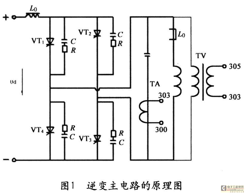
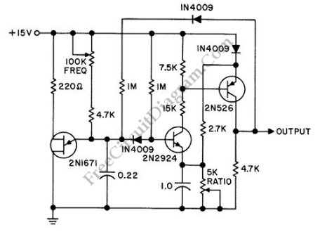
The main circuit schematic (Fig. 1) includes L0, which starts the magnetic ring, TA as a current transformer, and TV as a potential transformer, which provide feedback loops for measuring electric current and voltage signals, respectively. The feedback loop schematic (Fig. 2) features T, which isolates the voltage transformer, RP, a potentiometer for variable adjustment, and VDl-VD4, antiparallel diodes. The Zero Pressure Start method utilizes undesired signals to initiate self-excited oscillation, with the feedback loop capturing these signals. The controlling circuit amplifies and modifies the signal to output 180-degree control impulses synchronized with the load's oscillating frequency, controlling the triode thyristor of the bridge inverter.
The process begins when the circuit is energized, with various interference signals passing through an RC absorbing circuit and distributed capacitance, coupling to the load circuit. This interaction induces free oscillation in the LC circuit. The current transformer TA and potential transformer TV transmit oscillating current and voltage signals to the feedback loop, where they are combined to form a unified signal before being sent to the controlling circuit. This circuit generates impulse control signals that trigger the triode thyristor.
The key technological aspect of the Zero Pressure Start method is the ability to capture faint self-excited signals. A high transformation ratio of 1:500 in the feedback loop is employed for the current transformer TA. The four antiparallel diodes (VDl-VD4) operate in the linear region when the signal is weak, enabling higher output impedance and isolation from the voltage transformer T, which matches the circuit. During normal operation, VDl-VD4 presents minimal forward resistance, resulting in a high and balanced feedback signal. The voltage transformer T provides high input/output resistance, which enhances the input stage of the flip-flop and integrates with a high-sensitivity amplifying circuit.
Even with the faint self-excited signals captured, additional measures are taken to ensure effective triggering of the triode thyristor in the bridge inverter. This approach successfully utilizes the direct starting power of self-excited signals. The equivalent resistance of the resonant tank is low, which compensates for energy deficiencies, allowing for quick generation of valid self-excited signals at the load acceptor. Furthermore, the circuit incorporates time delay mechanisms to manage the self-excited signals effectively.The starting ability of the power of intermediate frequency is the most important performance index, quality and usability of its quality direct influence apparatus. So, it has focal point and difficult point that has studied in the industry to start the problem all the time, people adopt various methods to improve starting ability, for instance:
Charge and start the law, the self-excited law starts the law, separate excitation to rotate in parallel, magnetize and start the law etc. in advance, these methods have improved starting ability to a certain extent, but these traditional initialization modes are stored in circuit complicatedness, cost great, higher shortcoming of failure rate.
In order to reduce the equipment cost, optimize and simplify the device structure, find out a brand-new initialization mode in engineering practice -Zero pressure is started. This text explains its structural principle. It was a brand-new initialization mode that zero pressure was started, it has not increased any auxiliary apparatus extraly, the circuit is succinct, low cost, examined by long-term production practices, its starting ability is very superior.
Fig. 1 reverses the schematic diagram of the main circuit, L0 starts the magnetic ring, TA is a current transformer, TV is a potential transformer, offer for backfeed loop and measure the electric current and measure the voltage signal respectively. Fig. 2 is the schematic diagram of the backfeed loop, T isolates the voltage transformer, RP adjusts the potentiometer against the variable angle, VDl-VD4 is the antiparallel diode.
Zero pressure it starts to be to utilize undesired signal make it blow, shake not to support LC, produce self-excited oscillation, the backfeed loop catches the self-excited signal, the controlling circuit amplifies and has a facelift the signal, output 180 degrees of control impulses of synchronizing with oscillating frequency of load, phase place phase difference, control the triode thyristor of the bridge inverter. The concrete course is: When the circuit is energization, various interference signal passing RC absorbing circuit and distributed capacitance are coupled to the load circuit, striking and supporting LC makes it produce free oscillation, the current transformer TA, potential transformer TV transmit oscillating current and voltage signal to the backfeed loop, two signals superposed and formated in the backfeed loop, later sent into and reversed the controlling circuit, the controlling circuit produced the impulse control of signal and reversed the triode thyristor.
The technological key that zero pressure starts is how to catch the faint self-excited signal. Have adopted high transformation ratio 1 for this backfeed loop: 500Current transformer TA, last four diodes VDl-VD4 antiparallel, when the signal is faint, diode work in linearity region, thus can win higher output impedence and isolate the intersection of voltage transformer and T, match. In the normal working hour of power, VDl-VD4 presents minor forward resistance again, and the feedback signal is high and balanced.
T isolates the voltage transformer for high input / output resistance, goes against and changes input stage of the flip flop into the internal resistance of high input, high sensitive integrated amplifying circuit. Take even if self-excited signal can catch, go on, punish it while being faint behind the technical measure this, form the required effective triggering signal of triode thyristor of bridge inverter, has realized the purpose of using the direct starting power of self-excited signal.
Because the equivalant resistance of resonant tank is minor and supplements the deficiency of energy, the time to produce the valid self-excited signal in the acceptor of load is very short, in addition there are flights of steps leading to a palace hall of time delay in the circuit dealing with the self-excited signal, therefore is 🔗 External reference
Related Circuits
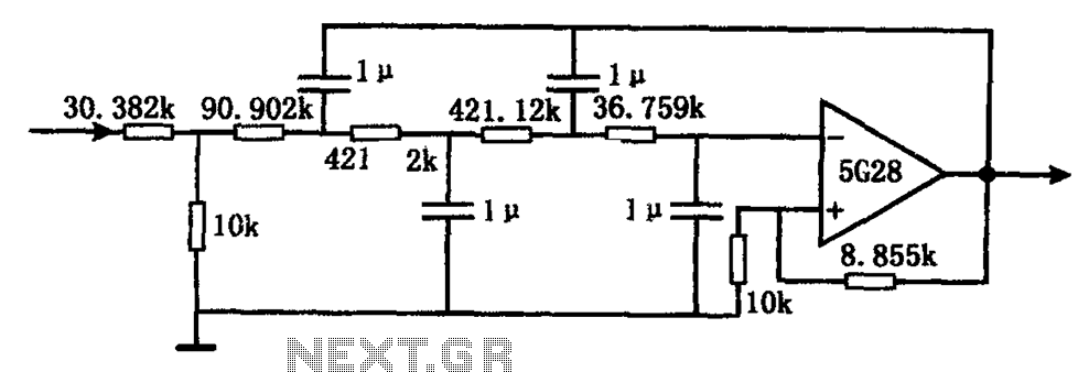
The circuit illustrated in the figure represents a staggered low-frequency active filter. This is a fourth-order Butterworth low-pass active filter designed to filter very low frequency (VLF) random pulse noise voltage at the DC level. The cut-off frequency is...
This circuit was designed and manufactured in the 1980s and has functioned without issues since then. It does not present any particular constructional problem, beyond the known: the attention in the provided force of power supply, choice of suitable...
An increasing number of appliances draw a very small current from the power supply. When designing a mains-powered device, one can typically choose between a linear power supply and a switch-mode power supply. However, if the total power consumption...
The RF engineer often needs an instrument that can reliably and quickly check a low-frequency quartz crystal unit. However, such equipment is challenging to find, and engineers frequently refer to electronic circuit handbooks for schematics that can perform this...
A discrete oscillator circuit illustrated in the schematic diagram below is a variable duty cycle and variable frequency oscillator, which can be utilized to generate various output waveforms. The discrete oscillator circuit is designed to produce oscillations with adjustable frequency...
The IEEE 802.3af standard defines the interaction between power-sourcing equipment and powered devices within a power-over-Ethernet system. The IEEE 802.3af standard, also known as Power over Ethernet (PoE), specifies the mechanisms by which electrical power is transmitted alongside data over...