
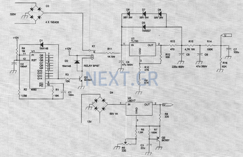
Power Supply with Adjustable Current and Voltage
The LM317 voltage regulator is designed to provide reliable and adjustable voltage output, making it suitable for various electronic applications. The device operates as a three-terminal positive voltage regulator with an output current capability exceeding 1.5 A and an adjustable output voltage range from 1.2 V to 37 V. To achieve optimal performance, careful attention must be given to the configuration of external components.
The programming resistors, R1 and R2, are critical for setting the output voltage. R1 should be placed as close as possible to the LM317 to minimize the impact of line resistance on the reference voltage. This placement helps maintain load regulation by reducing voltage drops that could affect performance. R2's ground connection should ideally be located near the load ground to enhance remote sensing and further improve load regulation.
Input stability is enhanced by using a bypass capacitor (Cin) of either 0.1 µF (ceramic) or 1.0 µF (tantalum) to mitigate sensitivity to input line impedance. Additionally, a capacitor (CAdj) connected to the adjustment terminal can be used to bypass it to ground, improving ripple rejection. A 10 µF capacitor is recommended to achieve approximately 15 dB of ripple rejection at 120 Hz, especially in applications with a 10 V output.
While the LM317 can function without output capacitance, the introduction of external capacitors can lead to instability in feedback circuits. To counteract this, an output capacitor (CO) of 1.0 µF (tantalum) or 25 µF (aluminum electrolytic) is recommended to ensure stability and prevent excessive ringing.
In applications where high capacitance values are utilized or when output voltages exceed 25 V, the inclusion of protection diodes becomes essential. Diode D1 prevents discharge of CO through the LM317 during input short circuits, while diode D2 protects against discharge of CAdj during output short circuits. This configuration safeguards the regulator's integrity during fault conditions.
The LM317's design incorporates internal features such as current limiting, thermal overload protection, and safe area compensation, contributing to its robustness and reliability. It is available in various packages, including surface-mount and standard through-hole configurations, allowing for flexibility in design and implementation. The LM317's versatility and ease of use make it an ideal choice for applications requiring adjustable voltage regulation, including local on-card regulation and programmable output configurations.The LM317 is capable of providing extremely good load regulation, but a few precautions are needed to obtain maximum performance. For best performance, the programming resistor (R1) should be connected as close to the regulator as possible to minimize line drops which effectively appear in series with the reference, thereby degrading regulation.
The ground end of R2 can be returned near the load ground to provide remote ground sensing and improve load regulation. A 0.1 µF disc or 1.0 µF tantalum input bypass capacitor (Cin) is recommended to reduce the sensitivity to input line impedance. The adjustment terminal may be bypassed to ground to improve ripple rejection. This capacitor (CAdj ) prevents ripple from being amplified as the output voltage is increased. A 10 µF capacitor should improve ripple rejection about 15 dB at 120 Hz in a 10 V application. Although the LM317 is stable with no output capacitance, like any feedback circuit, certain values of external capacitance can cause excessive ringing.
An output capacitance (CO) in the form of a 1.0 µF tantalum or 25 µF aluminum electrolytic capacitor on the output swamps this effect and insures stability. Protection Diodes When external capacitors are used with any IC regulator it is sometimes necessary to add protection diodes to prevent the capacitors from discharging through low current points into the regulator.
Figure 18 shows the LM317 with the recommended protection diodes for output voltages in excess of 25 V or high capacitance values (CO > 25 µF, CAdj > 10 µF). Diode D1 prevents CO from discharging thru the IC during an input short circuit. Diode D2 protects against capacitor CAdj discharging through the IC during an output short circuit. The combination of diodes D1 and D2 prevents CAdj from discharging through the IC during an input short circuit.
The LM317 is an adjustable 3terminal positive voltage regulator capable of supplying in excess of 1.5 A over an output voltage range of 1.2 V to 37 V. This voltage regulator is exceptionally easy to use and requires only two external resistors to set the output voltage.
Further, it employs internal current limiting, thermal shutdown and safe area compensation, making it essentially blowout proof. The LM317 serves a wide variety of applications including local, on card regulation. This device can also be used to make a programmable output regulator, or by connecting a fixed resistor between the adjustment and output, the LM317 can be used as a precision current regulator.
Output Current in Excess of 1.5 A Output Adjustable between 1.2 V and 37 V Internal Thermal Overload Protection Internal Short Circuit Current Limiting Constant with Temperature Output Transistor SafeArea Compensation Floating Operation for High Voltage Applications Available in Surface Mount D2 PAK, and Standard 3Lead Transistor Package Eliminates Stocking many Fixed Voltages 🔗 External reference
Related Circuits
All miniature electronic devices operate on batteries. Some require voltages higher than the standard battery voltages for efficient operation. When a battery of the specific voltage is unavailable, it becomes necessary to connect additional cells in series to increase...
The amplifier feeding the final amplification stage operates with unstabilized voltage. The output stage, utilizing push-pull operation, exhibits significant rejection of the supply voltage. However, the earlier stages do not provide the same level of rejection, resulting in unwanted...
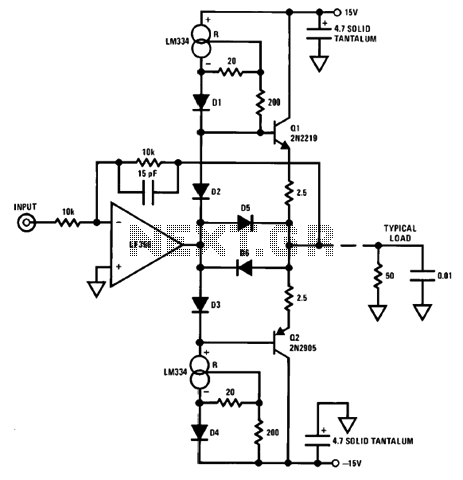
An output booster is required to achieve the necessary current or voltage gain. A significant output is often needed in conjunction with the output power limitations of most integrated circuit (IC) processors. The following figure presents a circuit diagram...
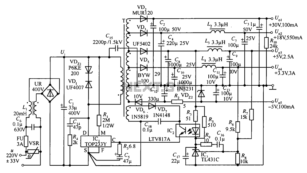
A 35W switching power supply circuit designed for a set-top box output is depicted in Figure 5. It features five distinct voltage outputs: Uo1 (+30V, 100mA), Uo2 (+18V, 550mA), Uo3 (+5V, 2.5A), Uo4 (+3.3V, 3A), and Uo5 (-5V, 100mA)....
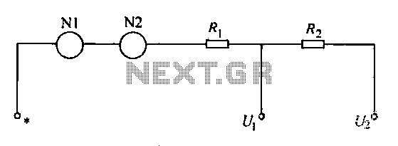
A voltmeter operates through a measuring mechanism in a specified circuit, utilizing a moving coil in series with additional resistance. The fixed coil is denoted as N1, while the moving coil is designated as N2. The additional resistances are...
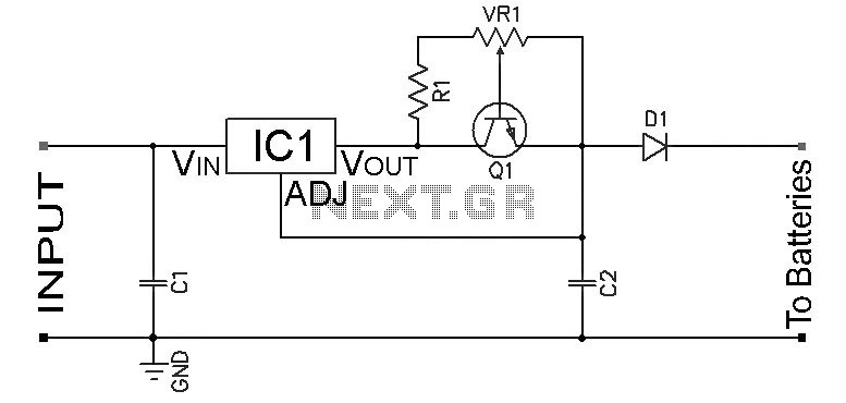
Adjustable Constant Current Ni-Cd and Ni-MH Battery Charger Circuit. This circuit is designed to provide a constant current for charging Ni-MH or Ni-Cd batteries. A schematic diagram of the circuit is available. The adjustable constant current battery charger circuit for...