
ATmega32u2 USB powered how to ground

In electronic circuit design, it is essential to ensure that the ground reference points are consistent throughout the system. When powering a microcontroller unit (MCU) via a USB connection, the common ground (zero voltage reference) must be connected to the supply voltage ground. This is critical to prevent potential ground loops and ensure proper operation of the MCU.
The USB interface typically provides a power supply of 5V, which is the standard voltage level for many microcontrollers. The 0V line, also referred to as the UVSS line, serves as the reference point for all voltage levels in the circuit. Properly connecting the UVSS line to the common ground of the USB power supply ensures that the MCU can accurately interpret signal levels and operate reliably.
In practical implementation, the circuit should include bypass capacitors near the MCU power pins to filter out noise and stabilize the power supply. Additionally, careful routing of ground traces is necessary to minimize inductance and maintain a low-resistance path to ground. This layout consideration is vital for high-speed digital circuits, where signal integrity can be adversely affected by poor grounding practices.
Furthermore, it is advisable to include protection components such as diodes to safeguard the MCU from potential overvoltage conditions that may arise from the USB connection. This protection will enhance the robustness of the circuit, ensuring that the MCU remains functional even under unexpected electrical conditions.
Overall, maintaining a consistent ground reference by connecting the common zero voltage to the UVSS line is a fundamental practice in electronic circuit design, particularly when integrating USB-powered microcontrollers.Because you are powering the MCU via USB, this common zero voltage should be the same as the supply and therefore connected to the 0V (UVSS) line. 🔗 External reference
Related Circuits
This kit is based on an original design by Jan G0BBL and serves as a versatile replacement for the older "Rocky" serial interface kit. It includes control of the programmable oscillator on the V6, 3 RXTX (and the older,...
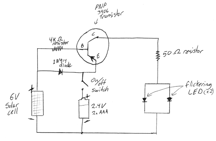
This is a DIY electronics project designed to enhance circuit design and building techniques. Copper lanterns were purchased and fitted with a circuit similar to outdoor solar lights. The circuit design is adapted from a simple design found on...

The reading lamp consists of a small solar panel, a standard UPS style lead acid battery, and an LED circuit board. The circuit board contains a low power solar charge controller (regulator), a set of 8 white LEDs, a...
Today, nearly all computers are equipped with logic blocks designed to implement a USB port. In practice, a USB port can deliver over 100 mA of continuous current at 5V to the peripherals connected to the bus. This capability...
This circuit switches a printer's USB connection from a PC to a laptop. The objective was to create a solution that enables a laptop to use the printer intermittently while maintaining the printer's primary connection to the PC. Instead...

The circuit consists of a grounded source and an emitter follower configuration. The source is grounded, and the emitter is combined with a common-collector transistor amplifier. As shown in the figure, VTI is a vibration-grounded field-effect transistor amplifier, while...