
power supply for 25 watts power amplifier based mosfet

The described power supply circuit is essential for ensuring the reliable operation of a 25W MOSFET power amplifier, particularly when utilized in high-performance audio applications. The power supply must deliver stable voltage and current to support the amplifier's demands, especially during dynamic audio playback.
To achieve the required performance, a step-down transformer with a minimum rating of 2kW is recommended. This transformer will convert the high-voltage AC mains supply down to a more manageable level suitable for the amplifier's operation. The transformer should be selected based on its efficiency and thermal performance to avoid overheating during prolonged use.
The power supply circuit also includes filter capacitors, which play a critical role in smoothing out the rectified output voltage. These capacitors must be rated for at least 300V to withstand the high voltages present in the circuit, particularly when dealing with tube amplifiers or high-power applications. It is advisable to use low-ESR (Equivalent Series Resistance) capacitors to enhance performance and reduce ripple voltage.
In addition to the power supply, the design incorporates a series of high-quality components that contribute to the amplifier's overall sound quality. The power and output transformers selected for this application should be capable of handling the required power levels while maintaining low distortion and high fidelity.
The power supply circuit is not only limited to the specified 25W MOSFET amplifier but can also be adapted for use with other audio devices, particularly those that require similar voltage and current specifications. Careful attention to component selection and circuit layout will ensure that the power supply remains reliable and efficient, ultimately enhancing the performance of the connected audio equipment.Power Supply for 25W Power Amplifier based MOSFET power supply. Go to that page to read the explanation about above power supply related circuit diagram. This Power supplycircuitispairedwith High Power audio amplifier 1500 watts. Power supply required for the amplifier requires a serious approach to the de sign. First you need a step-down transformer capacity of at least 2kW. Supply filter capacitors should be designed to. Thispower supplycircuit, is partof a series of Simple high-quality Tubeamplifierclass "A". Or maybe itcan be applied toother devices. Fewdetailedexplanation: Thecapacitorsin thePSU, aswellasC5in theamplifier-a voltageof 300V. Thepowerandoutputtransformers, usedin thisamplifier, tape recorderon "Astra4. " 🔗 External reference
Related Circuits
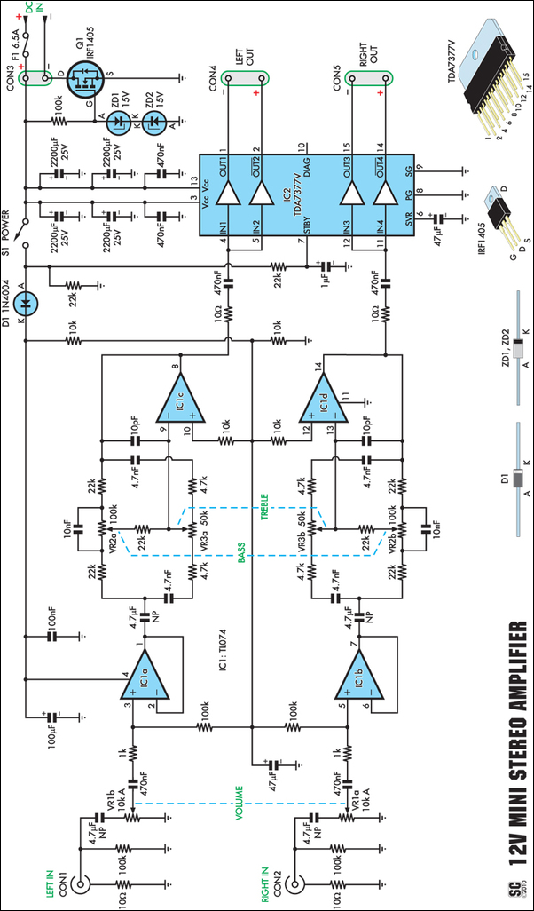
Amplifiers that operate on 12V DC typically do not produce significant power and are often not high fidelity. However, this compact stereo amplifier meets the requirements for power and low distortion. With a supply voltage of 14.4V, it can...
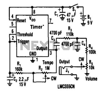
This metronome operates on a current of only 0.25 mA, making it suitable for battery-powered applications. It offers a tempo range from 34 to 246 beats per minute. The circuit can utilize a CMOS timer, such as the LM555...
High Quality unit with LM833 or NE5532 Low noise Dual Op-amp. No need for a preamplifier. Can be directly connected to CD players, tuners and tape recorders. Tested with several headphone models of different impedance: 32, 100, 245, 300,...
A small amplifier IC circuit has been compiled. This circuit is part of an older series and is categorized as a simple OTL (Output Transformer-Less) circuit. The presented small amplifier IC circuit is designed for applications where compact size and...
This low-cost project enables audio reproduction from a television without disturbing others. It eliminates the need for wired connections between the TV and loudspeakers. Instead, it utilizes invisible infrared light to transmit audio signals from the TV to the...

The AC negative feedback circuit consists of resistors R and R, as illustrated in Figure 1-30. In this configuration, capacitor C3 can be treated as a short circuit. The actual results are depicted in Figure 1-32. An AC voltage...