
OCL AC negative feedback amplifier analysis

The AC negative feedback circuit leverages the principles of feedback to stabilize and control the gain of an amplifier. The configuration typically includes a combination of resistors and capacitors, where resistors R6 and R7 play crucial roles in determining the gain and sensitivity of the circuit. The feedback mechanism provided by these components allows for improved linearity and reduced distortion in the output signal.
The formula for gain, K_v (1 + R7)/R6, indicates that the gain can be adjusted by varying the resistance of R7. This flexibility is essential in applications where precise control over amplification is required. By incorporating an adjustable resistor for R7, designers can fine-tune the gain to meet specific performance criteria.
The circuit's sensitivity S is a critical parameter that reflects how efficiently the amplifier responds to input signals relative to its output power capabilities. The relationship between the rated output power P and the circuit sensitivity can be expressed through the voltage levels at the output. Understanding this relationship allows engineers to design systems that can effectively handle varying input conditions while maintaining desired output characteristics.
Maintaining the symmetry of the differential amplifier circuit is vital for ensuring consistent performance. The adjustment of R2 in tandem with R7 is a design consideration that helps achieve this symmetry. By ensuring that R2 equals R7, the circuit can maintain balanced conditions, which is fundamental for minimizing common-mode signals and enhancing the overall stability of the amplifier.
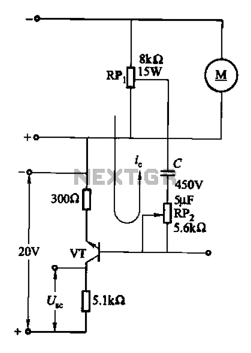
In summary, the AC negative feedback circuit is a sophisticated design that utilizes resistive and capacitive elements to create a stable and adjustable amplification system. The careful selection and adjustment of components such as R6, R7, and R2 are essential for achieving optimal performance in various electronic applications.AC negative feedback circuit is composed of R R and islands (Figure 1-30), since the C3 AC can be regarded as a short circuit, the actual results shown in Figure 1-32 o It is a n AC voltage series negative feedback o determines the gain of the negative feedback amplifier circuit (amplification circuit) o it is calculated as: K v (1 + R7)/R6. the gain amplifier circuit also determines the sensitivity of the circuit means that the circuit sensitivity S: reached yet rated input voltage when the output power is really needed, its size is determined by the voltage amplification circuit of calculating its decision.
law: Let rated output power P, then the voltage at the rated output power vo /W scale L, circuit sensitivity s V O/Ku. in general, the size of the gain adjustment circuit by changing the resistance R7 to carry out, so some circuit will be designed as an adjustable resistor R7.
it is worth noting that after changing the resistance of R7, R2 resistance should follow the change, so that R2 R7, which can keep the level of the differential amplifier circuit is symmetrical, to improve the stability of the circuit.
Related Circuits
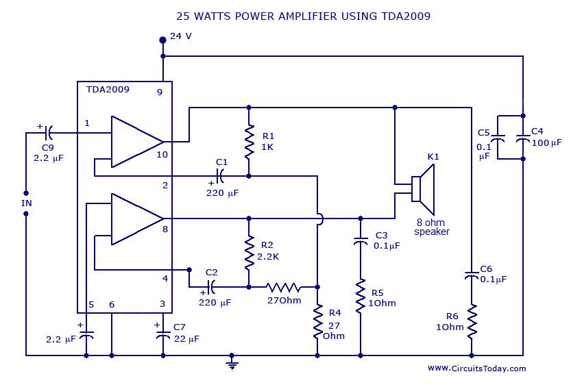
Power amplifier circuit diagram with schematics. This simple audio power amplifier circuit is designed for 25 watts output power using TDA 2009 IC, which has two channels (stereo), 12.5 W for each channel. The described power amplifier circuit utilizes the...
The amp is rated at 100W into a 4 Ohms load, as this is typical of a "combo" type amp with two 8 Ohm speakers in parallel. Alternatively, you can run the amp into a "quad" box (4 x...
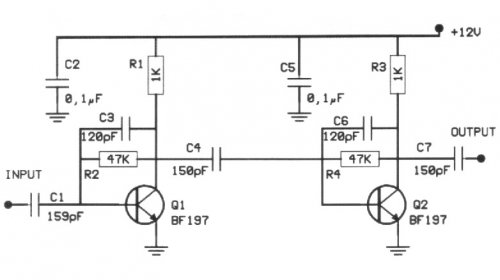
The following circuit illustrates a 20 dB VHF amplifier circuit diagram utilizing the BF197 transistor. Features include a simple circuit design. The 20 dB VHF amplifier circuit is designed to amplify very high frequency signals, making it suitable for applications...
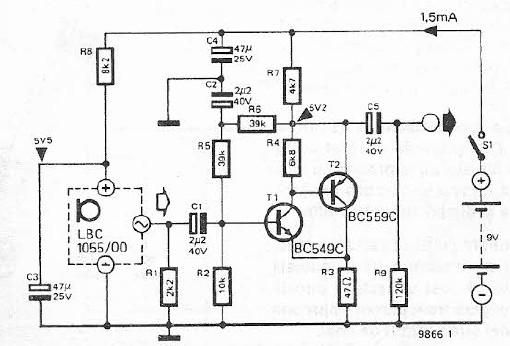
This electret microphone amplifier is constructed using standard electronic components. It is designed to work with an electret microphone capsule, although it can also accommodate a dynamic microphone that has low resistance. The circuit operates with a supply voltage...
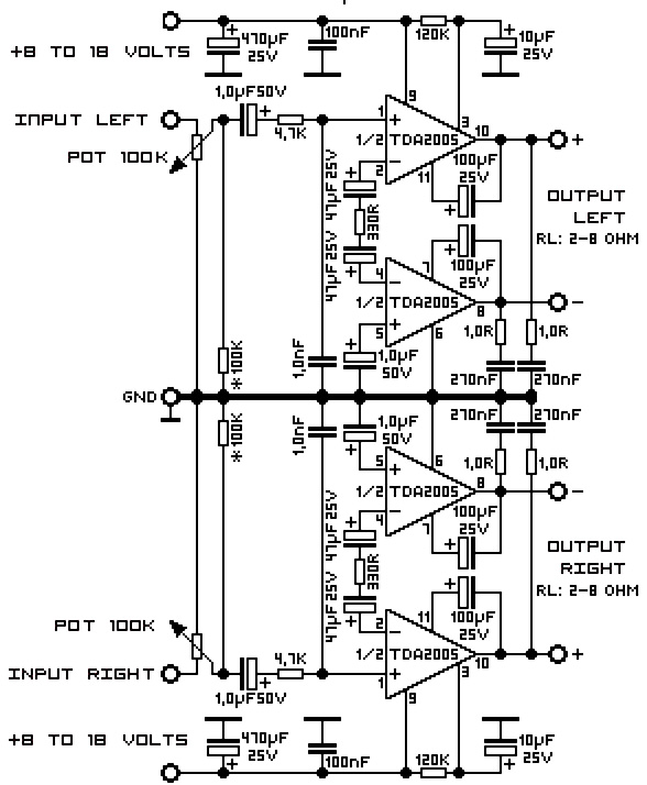
A 20W TDA2005 stereo amplifier designed for various applications, including the amplification of medium power speakers. It is suitable for automotive use; however, the power supply must be equipped with a choke of at least 150mH and should provide...
After integrating the negative feedback circuit, the adjustment object and inertial measurement feedback link are susceptible to oscillations. To address this, a voltage differential or speed differential circuit is employed to minimize or eliminate these oscillations, serving as a...