
powerful dc to ac converter schematic
This circuit utilizes the CD4047 integrated circuit, which is capable of generating square wave signals at the desired frequency. The frequency output can be adjusted based on the external components connected to the IC. The MOSFET IRFZ44 is chosen for its efficiency and ability to handle high currents, making it suitable for driving the induction transformer. The transformer’s role is crucial, as it steps up the voltage from the low DC input to a high AC output, which is essential for applications requiring AC power.
The output waveform, primarily a square wave, can be smoothed out with the inclusion of a filter capacitor (C3). This capacitor helps to reduce the harmonic content of the output, resulting in a waveform that is closer to a sine wave, which is more suitable for powering sensitive electronic devices.
When designing for higher power applications, it is important to ensure that the MOSFETs are rated for the required current and are adequately cooled to prevent overheating. Parallel configuration of MOSFETs allows for increased current handling capabilities, thus enhancing the overall performance of the converter.
The choice of transformer is also critical; a 9V center-tapped transformer is often favored due to its efficiency in stepping up voltage, while a 12V center-tapped transformer may lead to increased losses and reduced performance. Proper selection of battery voltage and current rating is essential for achieving the desired output wattage, ensuring that the system operates efficiently and reliably.
Overall, this simple DC to AC converter circuit is effective for low-power applications and can be adapted for higher power needs with careful component selection and configuration.This circuit is very simple less than 12 component, to build DC to AC converter. The principle of this circuit is generating 50/60Hz frequency by IC CD4047 and the output complement pin 10 and 11 of IC CD4047 to drive MOSFET IRFZ 44 so induction primary transformer is work and get high voltage at out secondary transformer about 220V AC. The output converter wave is still square wave and more close to sine wave with filter C3 220nF. For more high current output (wattage) use high current battery and the MOSFET must be parallel. For example to get 240W output the battery used is 20A. Or if you use 24V CT transformer you just only use battery 24V/10A. In practice report the commonly is use 9V CT transformer will step up to high voltage output, if using 12V CT transformer were dissatisfied because transformer losses. 🔗 External reference
Related Circuits

Utilizing sunlight as a power source can help reduce electricity costs. Below is a description of a simple power plant that can be created to charge a motorcycle battery or power emergency lights. Solar panels capture sunlight and convert...
The figures below illustrate using opamps as active 2nd order filters. Three 2nd order filters are shown, low pass, high pass, and bandpass. Each of these filters will attenuate frequencies outside their passband at a rate of 12dB per...
The speed of the display can be adjusted as desired. The output from the 555 timer is directly connected to the input of a CD4017 decade counter. The input of the counter is referred to as the CLOCK line...
The result displayed on the LCD is incorrect; the thermometer shows a reading of 414 degrees instead of the actual room temperature. Assistance is needed to determine whether the issue lies within the hex file or the sensor itself....
The purpose of this timer is to disconnect the compressor circuit and connect a resistive heating element located near the evaporator at regular time intervals. The defrost heater is controlled by a thermostat and is used to melt any...
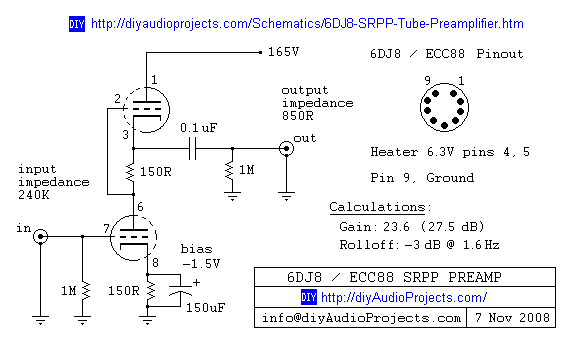
6DJ8 / ECC88 Symmetrical SRPP Tube Preamplifier Schematic. The gain of the preamp is 27 dB (approximately 23.5 times). The 6DJ8 / ECC88 symmetrical SRPP (Shunt Regulated Push-Pull) tube preamplifier schematic is designed to provide a high level of gain...