
analog to digital converter pic
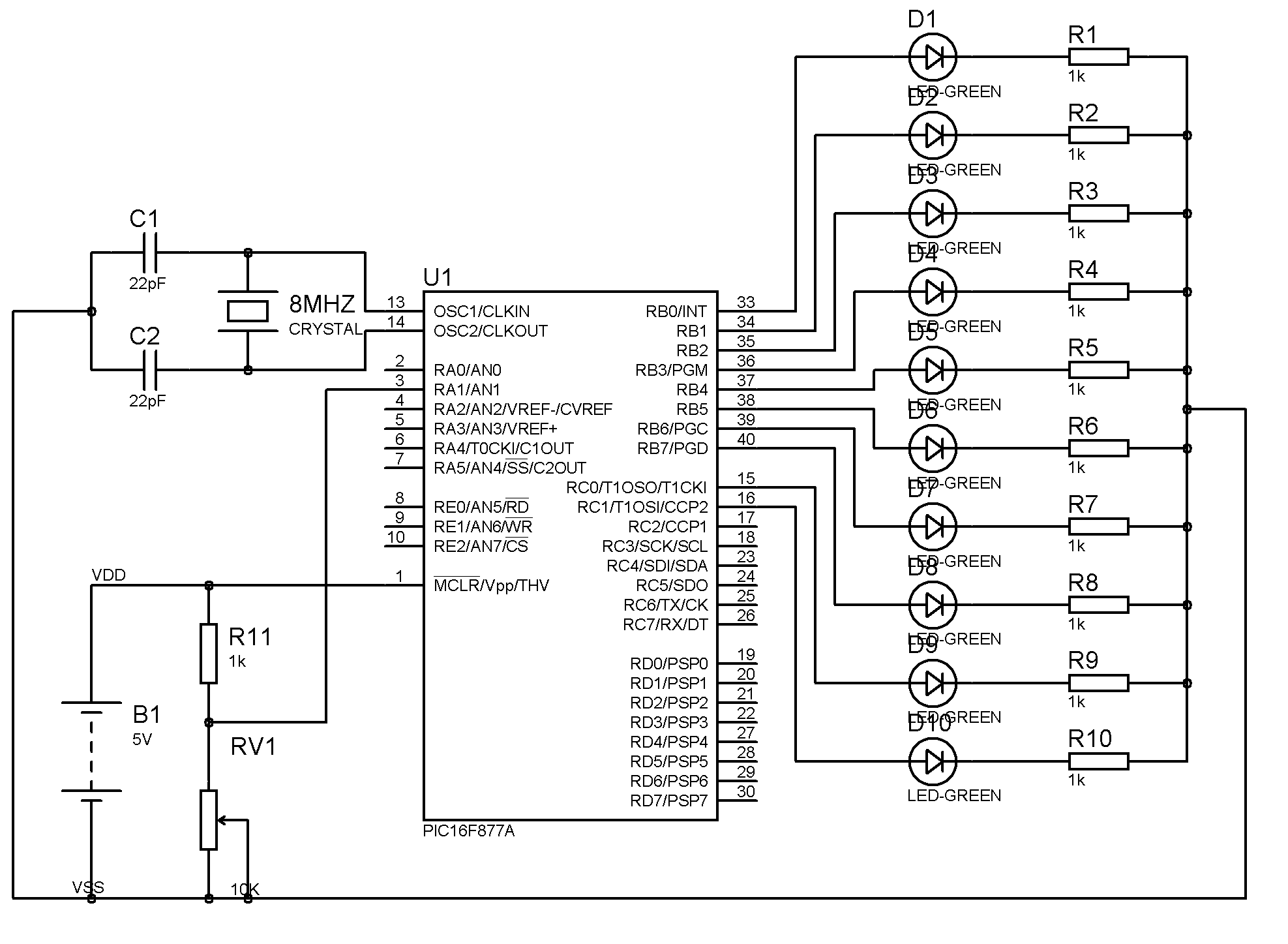
The LCD displaying an incorrect temperature reading may indicate a fault in the sensor calibration or a programming error in the hex file. The connections for Vref+ and Vref- should be verified to ensure they correspond to the expected voltage levels required for accurate sensor operation.
For the IR motor speed control, the circuit will consist of an IR transmitter and receiver, a microcontroller, a motor driver, and an LED indicator. The microcontroller will interpret the signals from the IR receiver, adjusting the motor speed accordingly. The increment and decrement functionality will be implemented using two buttons that modify a speed variable within the microcontroller's firmware. The LED will serve as a visual feedback mechanism, with its state changing based on the speed level.
Regarding the use of a 20 MHz crystal, it is essential to understand that microcontrollers can often utilize different clock frequencies through configuration settings or external circuitry. However, if two applications require different frequencies, it may necessitate additional components such as frequency dividers or multiplexers to manage the clock signals effectively.
For the analog-to-digital converter (ADC) task, a 2-bit output can be achieved through a simple mapping of the input voltage range (5V to 12V) to the output values (00, 01, 10, 11). The ADC design should include a reference voltage setup that ensures the input range is accurately represented in the digital output.
To enhance the resolution of voltage and current measurements using a 10-bit ADC, consider employing signal conditioning techniques such as amplification or filtering to improve the input signal quality. Additionally, using averaging algorithms in the firmware can help mitigate noise and provide a more precise output.
The communication of port numbers in binary format (e.g., 0xff = 11111111) indicates the ability to control multiple inputs or outputs on a microcontroller. Understanding how to manipulate individual bits will allow for fine control over the system's behavior.The G‚result of the lcd is not correct the thermometer does not show the room temperature but show the 414 degree then i need to know where is the problem is it in the hex file or in the sensor note (i connect vref+ on5v . and vref- on 0v) thanks for your care hi can you teach me a code for a IR motor speed control. using a program which can read a increment or decrement of speed and will vary the speed of the motor. The increment and decrement is based on the transmitter part of the IR transmitter. thanks a lot and also there is a LED that will indicate the degree or level how fast the speed of the motor. for example. when you turn on the device, there is only one LED that is on, then when the increment button is pressed, the second LED will turn on.
When the decrement button is pressed, the second LED will turn off and will return to only one LED is on. Hii In every tutorial different frequency of crystal has been used. but my board contains only 20Mhz crystal . but how will it be posssible to use different frequency crystal at the same for the two applications which are going to be perfermed simultaneously.
hi my company have given me a task to create analog to digital converter with max input voltage 12v and min input voltage 5v. but the output must be in 2 bit. meaning that if input 12 v, the output will be 11 and so on. can u help me Hi, I have gone through your volt and currnet measurement. I have voltage range from 0-50 and current range from 0-1A. As per you calculation presented I get very poor resolution. Can you please explain how to get better resolution through the range using 10 Bit ADC Hi albhee, 0xff (HEX) = 11111111 (BIN) = 75643210 (Ports number), if you want only one 00000001 = port 0 input also if want anhother 00001000 = port 3 input.
🔗 External reference
Related Circuits
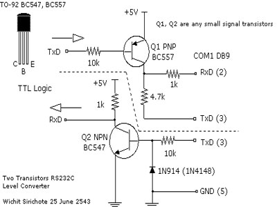
To connect a microcontroller project to the COM port of a PC, an RS-232 converter is required. Various chips are available to address this need, such as the MAX232 and DS275. The RS-232 standard is widely used for serial communication...
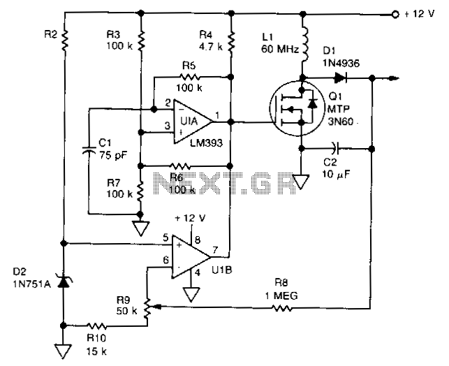
U1 is a dual voltage comparator with open collector outputs. The A side functions as an oscillator operating at 100 kHz, while the B side is part of the regulation circuit that compares a fraction of the output voltage...
There are monitors that feature only three BNC inputs and utilize composite synchronization (sync on green). This circuit has been specifically designed for such monitors. The design maintains simplicity while delivering reasonable performance. The operational principle is straightforward. The...
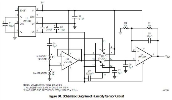
If a sensor is resistive, an alternating current (AC) is equivalent to pulsed direct current (DC), and the sensor will degrade based on the root mean square (RMS) value of the AC signal. Applying 1V AC RMS is effectively...
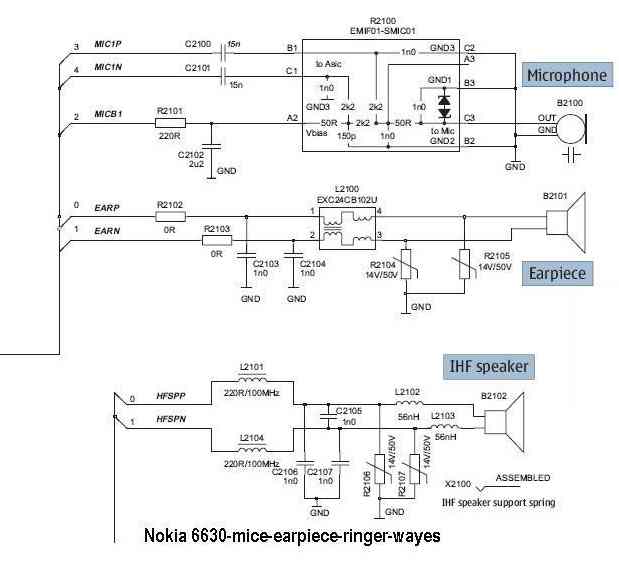
The microphone issue on the Nokia 6630 is typically attributed to several factors, including a damaged microphone, a broken circuit path, or a faulty UEM IC. If the issue arises from a broken path in the microphone circuit, it...
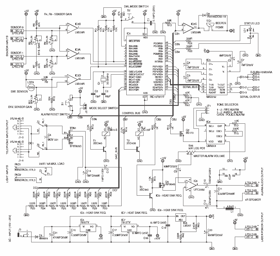
This system uses a Microchip's PIC16F877A as a main controller, LM339 as sensor interface, UM3561 as a tone generator and PC2002 as a speaker driver (audio amplifier). LM7805, LM7812 and LM317 voltage regulators are used to obtain +5V, +12V...