
PQS1 series magnetic disk control panning control circuit
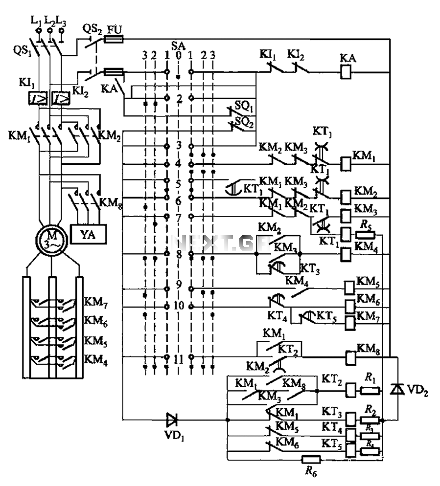
The described system integrates a master controller with a PQS1 Series Magnetic control panel, which serves as the central unit for managing the operational parameters of the bridge crane hoist. The control circuit is meticulously designed to facilitate precise control over the lifting and lowering mechanisms of the crane.
The master controller handle SA, with its seven distinct positions, provides operators with the flexibility to select from three different lifting speeds, enhancing operational efficiency based on the load requirements. The zero position serves as a safety feature, engaging the parking brake to secure the crane when not in operation.
The three drop blocks are critical for managing the descent of the load. The second block is specifically intended for single-phase braking, allowing for controlled lowering of the load. The forced descent feature, activated by the first three blocks, ensures that the crane can safely lower heavy loads under specific conditions, thereby preventing uncontrolled descent.
The timing mechanisms, including the motor delay of 0.65 seconds and the relay KTi's pull and off delays, are essential for ensuring the safety and reliability of the system. The motor delay prevents abrupt stopping that could lead to a heavy slip of the hook, while the relay delays serve to extend the contact access time, effectively minimizing the risk of phase short circuits. These features collectively enhance the operational safety and efficiency of the bridge crane hoist, making it suitable for various industrial applications where precise load handling is crucial. By master controller and PQS1 Series Magnetic control panel consisting of a control circuit for controlling the bridge crane hoist lifting mechanism of control. Master controll er handle SA has seven positions: In addition to the zero position, there are three lifting gear, lift speed can be obtained in three different degrees; there are three drop block, the second block for the single-phase brake down first 3 block is forced down if it is the weight of the transition to a system for generating motion decline; first stop only when pulled from the first block of the first block 2, 3, in order to pull down the brake for fall, nowhere else. Zero parking brake when YA first action, the motor delay o. 65s after power to prevent stopping power generated with heavy slip hook. Commutation of the relay KTi pull delay is 0.11N0.16 s, off delay is 0.15 ~ 0. 2s, the main purpose is to extend contacts for access time, to avoid phase short circuit.
Related Circuits
Color sensing using a camera and a sufficiently powered processor that runs image histogram logic (or similar algorithms) can reliably determine the presence of specific colors. However, alternatives that are significantly more cost-effective for detecting the presence or absence...
The 3D printer necessitates independent control for three separate axes. Each controlled axis must be equipped with a high-precision electronic driver. The mechanical components of each axis utilize a precise bipolar stepper motor connected to a drive shaft via...
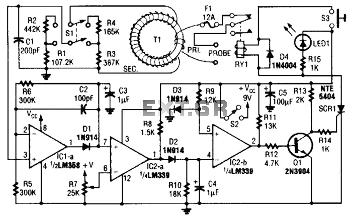
This circuit is an adjustable electronic circuit breaker that features a toroidal transformer designed to sense a 60-Hz load current. The transformer, labeled as T1, has a two-turn winding for the primary side and 100 turns of #30 gauge...
One-farad capacitors require some care. It's common knowledge that they must be pre-charged with a current-limiting resistor before plugging in. It is less common knowledge that those fifty-dollar smart cap controllers are in fact very simple devices, two dollars...
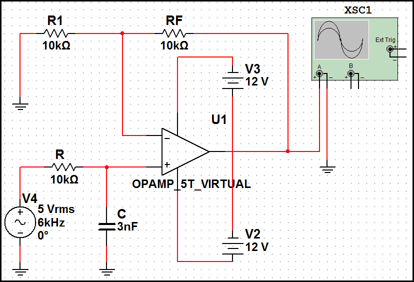
High-order filters are typically designed with two or more cascaded sections. An order 4 filter requires only one operational amplifier integrated circuit (OA IC), allowing for lower distortion. High-order filters are essential in various applications, including audio processing, signal conditioning,...
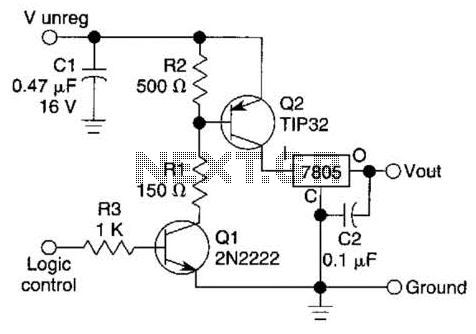
A logic level can control a 7805 regulator with this circuit. Q2 is a series switching transistor controlled by Q1. Q1 is turned on by a logic voltage to its base. This circuit utilizes a 7805 voltage regulator, which is...