
stepper motor control
The described circuit operates with a focus on efficiency and precision in controlling the stepper motors necessary for 3D printing applications. The use of the TI DRV8818 driver allows for advanced control features such as current decay modes and integrated H-bridge functionality, which enhances the overall performance and reliability of the stepper motor operation. The design minimizes the load on the processor through integrated functions and simplified control signals, making it suitable for applications requiring compact and efficient electronic designs. The choice of components and their configurations, including the chop current settings and the management of active and inactive states, are critical for maintaining the desired motor performance while ensuring energy efficiency. The implementation of current sensing resistors and the ability to set the chop current through external components provides flexibility in tuning the motor characteristics for various printing requirements. Overall, this circuit design exemplifies a sophisticated approach to managing stepper motor control within a 3D printing system, emphasizing precision, efficiency, and ease of integration.The 3D printer requires separate control for three independent axis. Each of the controlled axis must have a high precision electronic driver. Mechanical part of the each axis is based on a precise bipolar stepper motor connected to a drive shaft via claw coupling. An additional driver and mechanics are used for the extruder. The stepper motor con trol is based on a TI DRV8818. The DRV8818 is an improved version of the TI DRV8811. Main difference between these two devices is in the value of the ON-resistance of the DRV8818 output MOSFET. A direct dependence of total power dissipation (TPD) over the device and ON-resistance is a critical parameter when running motors at higher levels of currents.
Roughly calculated, difference of the ON-resistance between the two before mentioned devices is 0. 6 ©. At the peak current value, TPD of the DRV8818 is 1. 46 W and is lower by 2. 37 W then it would be if the DRV8811 was selected. Both DRV8811 and DRV8818 are fully functional stand alone stepper motor drivers. The integration of various functions in single IC package decreases the requirements on the processor unit. The processor unit controls only three signals per driver. This allows minimal MSP430 processor pin usage per driver device and that was one of the important parameters for a project design.
Furthermore, the stepping sequence for the motor is realized by the DRV8818 internal step indexer logic which also reduces the computational burden on the processor unit. The DRV8818 supports advanced current routing for motor windings realized by an integrated H-bridge. Integration of the H-bridge inside the DRV8818 package reduce the number of external discrete elements and improves matching and thermal equilibrium between the transistors.
The transistor switches used in the H-bridge are protected from the voltage spikes caused by turning the power off in a motor winding by the integrated fast schottky diodes. In chematic presented below the single stepper motor driver is presented. The chop (peak) current is defined by the trimmer R18 connected in series with the resistors R19 and R110.
The ICHOP is calculated by an expression ICHOP = VREF / (8RSENSE). In this case, the voltage VREF, min is 0. 17 V, and the voltage VREF, max is 1. 59 V. The minimum and maximum values of the voltage VREF define the currents ICHOP, min at 0. 21 A, and ICHOP, max at 1. 99 A. The current sensing resistors R11 and R12 have resistance of 0. 1 ©. The activation of the driver is controlled by ACTIVE signal. The ACTIVE signal allows the processor to shut off the output stage of the DRV8818. During the period between two steps of the motor, the output stage is inactive. When the ACTIVE signal is low, all functions of the device are suspended and the device is in a low power state. Stepping of the motor is controlled with the rising edge of the impulses on the STEP terminal. The maximum stepping frequency of 500 kHz is defined by the device data sheet. The wake-up time is the time interval needed for the device to become fully active after the signal on the ACTIVE terminal is changed from a low to high, in order to prevent loosing step impulses or other irregularities.
Selected value was experimentally confirmed as the correct choice. The signal on the DIRECTION terminal selects the clockwise or the counter clockwise rotation of the stepper motor. The direction of rotation is selected upon the terminal voltage level. The DRV8818 supports two current decay modes. In this project fast decay mode is selected. The mode selection is done by grounding the DECAY terminal. The full step indexing mode is selected by grounding terminals USM0 and USM1. 🔗 External reference
Related Circuits
Have you ever imagined controlling your home appliances using your cell phone? Numerous circuits exist for this application, typically utilizing a telephone. This circuit has been modified and redesigned for compatibility with a standard cell phone headphone jack. To...
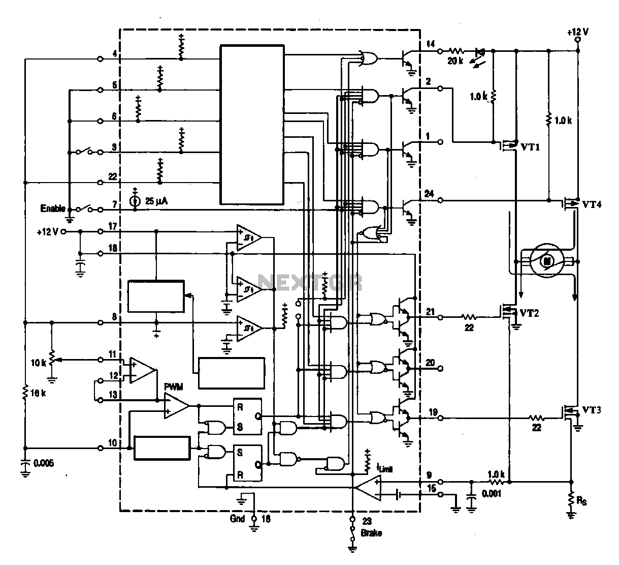
A DC brush motor driver circuit diagram utilizing the MC33035 chip is presented, illustrating a typical configuration for driving a straight DC brush motor. The circuit incorporates a field-effect transistor (FET) bridge driver setup. When transistor VT3 is activated,...
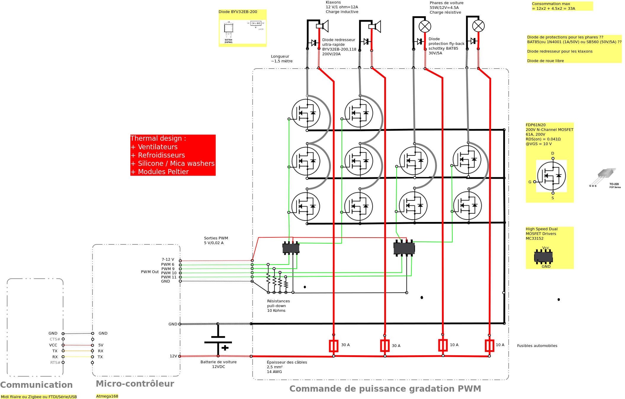
Past experiences were quite challenging due to the inductive nature of car horns, which require 12A of current, with peak demands reaching 20 to 30A. The current electronic system lacks reliability, given the high intensity. There is a need...
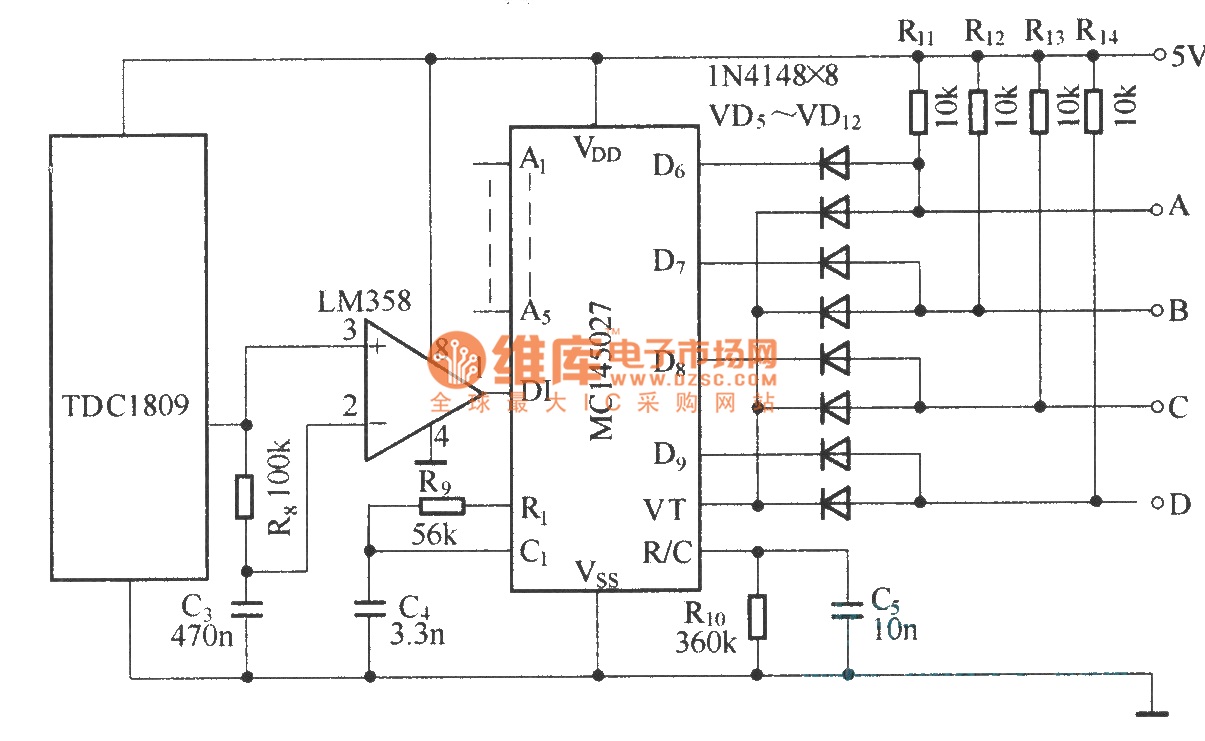
The TDC1808/TDC1809 is a pair of wireless remote control transmitter and receiver components. They utilize an internal antenna to transmit both digital and analog signals. These components are suitable for various wireless remote control devices. Key features include compact...
Is there a circuit that can be used to make a DC motor move randomly backward and forward, stop for a period, and then start again? Any assistance and ideas would be greatly appreciated. Research how to wire up...
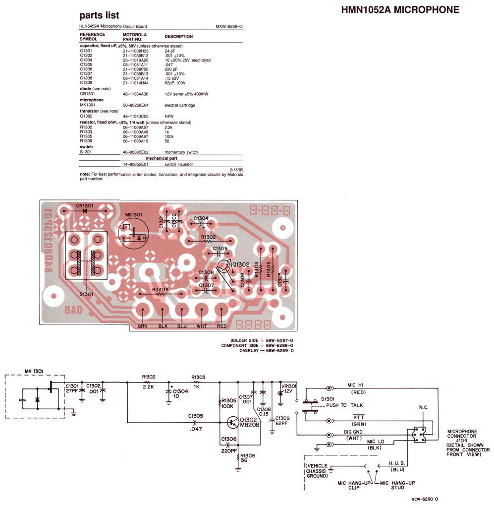
Regardless of the label on the radio or the claims made by the seller, no Spectra radio will function across the entire 136-174 MHz (high band) or 403-512 MHz (UHF) frequency range. Each unit operates within a specific portion...
Warning: include(partials/cookie-banner.php): Failed to open stream: Permission denied in /var/www/html/nextgr/view-circuit.php on line 713
Warning: include(): Failed opening 'partials/cookie-banner.php' for inclusion (include_path='.:/usr/share/php') in /var/www/html/nextgr/view-circuit.php on line 713