
7805 Turn-On Circuit Circuit
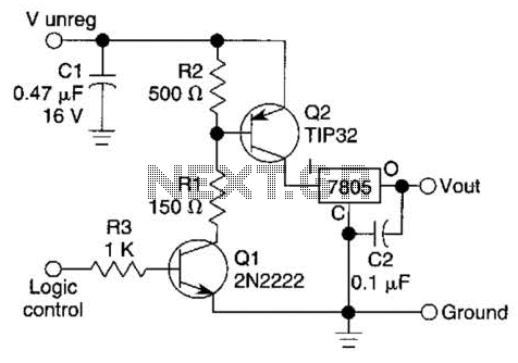
This circuit utilizes a 7805 voltage regulator, which is designed to output a stable 5V supply from a higher input voltage. The control mechanism is implemented via two transistors, Q1 and Q2. Q1 functions as a control switch that is activated by a logic-level voltage applied to its base. When this voltage is present, Q1 enters the saturation region, allowing current to flow from its collector to its emitter. This action effectively turns on Q2, which is configured as a series switching transistor.
Q2, when activated by Q1, connects the output of the 7805 regulator to the load. This configuration enables the circuit to control the power delivery to the load based on the logic-level signal applied to Q1. The 7805 regulator maintains a constant 5V output as long as the input voltage remains within the specified range and the load does not exceed its current rating.
In practical applications, this circuit can be used in microcontroller-based systems where a digital output pin can control the power to various peripherals or components. The use of transistors allows for efficient switching, minimizing power loss and heat generation compared to mechanical relays. Proper biasing of the transistors is essential to ensure reliable operation, and appropriate resistor values should be selected to limit the base current for Q1 while ensuring that Q2 can handle the load current without entering the saturation region excessively.
Additionally, it is advisable to include bypass capacitors near the input and output of the 7805 to stabilize the voltage and filter out noise, ensuring clean power delivery to the connected load. A logic level can control a 7805 regulator with this circuit. Q2 is a series switcliing transistor controlled by Ql. Ql is turned on by a logic voltage to its base. 🔗 External reference
Related Circuits
The circuit of the unit is fairly simple, but is a bit irksome to set up. The reason is that obtaining matched FETs is not easy, so I had to make sure that the circuit would work with off-the-shelf...
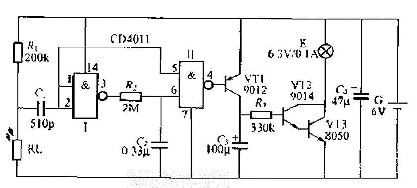
This is an automatic light dimmer circuit that eliminates the need for manual adjustment of light levels. It utilizes a Light Dependent Resistor (LDR) to detect ambient light conditions, which in turn controls a Triac to adjust the brightness...

This design features a simple yet effective receiver with good sensitivity and selectivity. The circuit utilizes a compact three-transistor regenerative receiver with fixed feedback, primarily based on the BC549 transistor. The tuned circuit is intended for medium wave frequencies...
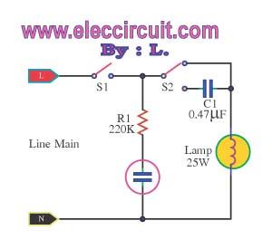
A battery-powered light control circuit is designed to delay the lighting of a small lamp during sudden power outages or nighttime situations when a blown fuse leaves a room in darkness. This circuit addresses the difficulty of locating matches...
A circuit was required to function as a bass boost. The design was adapted from a circuit by ESP Sound, focusing solely on the frequency range of 35-150 Hz. The bass boost circuit, as adapted from the original design, primarily...
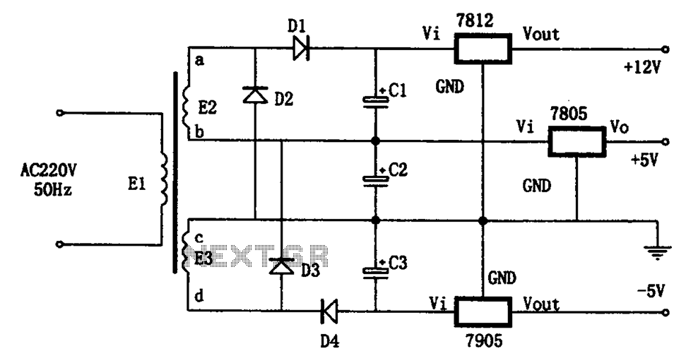
The circuit illustrated in the figure represents a specialized power supply configuration. It is straightforward in design and can be constructed using two identical secondary windings to generate three distinct DC voltage outputs: +5V, -5V, and +12V. The circuit...
Warning: include(partials/cookie-banner.php): Failed to open stream: Permission denied in /var/www/html/nextgr/view-circuit.php on line 713
Warning: include(): Failed opening 'partials/cookie-banner.php' for inclusion (include_path='.:/usr/share/php') in /var/www/html/nextgr/view-circuit.php on line 713