
Practical Method for Production of Water Fuel with Piezoelectric
Warning: Undefined array key "extension" in /var/www/html/nextgr/view-circuit.php on line 477
Deprecated: strtolower(): Passing null to parameter #1 ($string) of type string is deprecated in /var/www/html/nextgr/view-circuit.php on line 477

The circuit described functions as a remote control switch utilizing ultrasonic sound, which operates at frequencies above 20 kHz, rendering it inaudible to humans. The transmitter component generates ultrasonic sound within the frequency range of 40 to 50 kHz using a 555 timer configured as an astable multivibrator. This design effectively drives an ultrasonic transmitter transducer, powered by a 9-volt battery. The receiver circuit employs an ultrasonic receiver transducer to detect the ultrasonic signals emitted by the transmitter. It consists of a two-stage amplifier, a rectifier stage, and an operational amplifier (op-amp) in inverting mode. The output from the op-amp is connected to a relay through a complementary relay driver stage, allowing for the control of external devices.
When the switch (S1) on the transmitter is activated, it generates ultrasonic sound that the receiver transducer picks up, converting it into electrical variations. These signals are amplified by transistors T3 and T4, then rectified and filtered to produce a DC voltage. This voltage is applied to the inverting pin of the op-amp (IC2), while the non-inverting pin receives a variable DC voltage via a preset resistor (VR2), which sets the threshold for the ultrasonic signal required for relay activation. This system can be adapted for various applications, including the proposed integration with the humidifier transducer, ensuring efficient operation within the designated frequency range.His transducer is out of a humidifier and it operates at 48 Khz. It has the driver circuit too. Easy access for mods. I may have to go to walmart. From the looks of things, as I am taking apart one of the two transducers I have - They look like they`re not going to give up their little circutboard easily. This leads me to the conclusion, we will effectively have to build our own circutboard, or find one. Is there any way we can have circutboards made through an onlinecompany, and then distributed through this group I might know a few of them that wouldn`t be too expensive. Like I said though - It is not my area of expertise. I do not think I have the technical-know-how to build one of those things from scratch. I`m currently looking up the how-to`s - but I think there must be a faster way. So, what I am proposing, is to make a joint effort to create the circutboard/oscilator circut, and then we would purchase them, distribute them - and effectively have the same working oscillator on the transducer in the end.
I could then put the spark gap outside the pipe, and into a secondary mist chamber. The primary "mister" would be governed by the "influencer" to produce more HHO. The secondary chamber would be towards adding more water vapor, so that the mixture does not become too HHO rich. petar113507, Is the item in your hand in the last picture the inside bottom (or top) of the ultrasonic fogger If so it`s no surprise that it appears to be encased in silicone or some other potting material since the unit has to be underwater.
If it`s silicone rubber like it may be possible to peel away the silicone to get at the circuit but if it`s a harder material it`s probably going to difficult to avoid damaging the circuit. I think it would be fairly easy to build a circuit but I would mostly be concerned about how well it would work with the existing disk if the frequency is much higher that the circuit feeding it now.
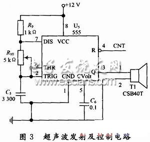
The circuit below would be simple enough and is variable by VR1 from 40 to 50 Khz which is right in our target range. Circuit description below from : "Circuit of a new type of remote control switch is described here. This circuit functions with inaudible (ultrasonic) sound. Sound of frequency up to 20 kHz is audible to human beings. The sound of frequency above 20 kHz is called ultrasonic sound. The circuit described generates (transmits) ultrasonic sound of frequency between 40 and 50 kHz. As with any other remote control system this cirucit too comprises a mini transmitter and a receiver circuit.
Transmitter generates ultrasonic sound and the receiver senses ultrasonic sound from the transmitter and switches on a relay. The ultrasonic transmitter uses a 555 based astable multivibrator. It oscillates at a frequency of 40-50 kHz. An ultrasonic transmitter transducer is used here to transmit ultrasonic sound very effectively. The transmitter is powered from a 9-volt PP3 single cell. The ultrasonic receiver circuit uses an ultrasonic receiver transducer to sense ultrasonic signals. It also uses a two-stage amplifier, a rectifier stage, and an operational amplifier in inverting mode.
Output of op-amp is connected to a relay through a complimentary relay driver stage. A 9-volt battery eliminator can be used for receiver circuit, if required. When switch S1 of transmitter is pressed, it generates ultrasonic sound. The sound is received by ultrasonic receiver transducer. It converts it to electrical variations of the same frequency. These signals are amplified by transistors T3 and T4. The amplified signals are then rectified and filtered. The filtered DC voltage is given to inverting pin of op-amp IC2. The non- inverting pin of IC2 is connected to a variable DC voltage via preset VR2 which determines the threshold value of ultrasonic signal received by receiver for operation of rel 🔗 External reference
Related Circuits

The sensor must be positioned at an angle of approximately 30 to 45 degrees relative to the ground. This orientation facilitates the drainage of rainwater, preventing accumulation that could trigger the alarm due to water retention on the sensor....
The FIG inverter I, II, along with resistors R1, R2, capacitor CI, and switch SB, forms a bistable trigger switch. Each time switch SB is activated, the output level of anti-phase II changes. The circuit includes components R3, C2,...
The water tank overflow liquid level sensor alarm circuit is a straightforward electronics project suitable for school students. Previous discussions have covered numeric water level indicators and water level controller circuits, which are more complex and intended for engineering...
The analog computer was initially simulated using Multisim 7. Following this, an analog simulator circuit was constructed on breadboards using discrete and integrated components. A function generator was utilized to provide the road surface as input, and the output...
The defect that cannot be overcome exists in certain circumstances with traditional distance measuring methods. For instance, the measurement of liquid levels is a type of range measurement where traditional electrode methods involve the placement of electrodes to measure...
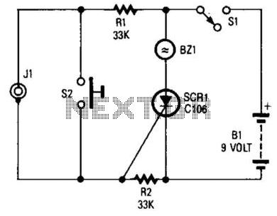
If you choose to create your own moisture sensor, this foil pattern will be useful. A sensor connected to J1 activates CR1, which sounds buzzer BZ1. The sensor consists of a printed circuit board (PCB) foil pattern grid. Multiple...