
Contactless air range finding method on the basis of P89LPC932

The ultrasonic measurement system is designed to overcome the limitations of traditional distance measuring techniques, particularly in environments where electrodes may fail due to corrosion or sensitivity loss. The use of ultrasonic waves eliminates the direct contact issues associated with liquid measurements, providing a more reliable and durable solution.
This system's operational principle relies on the time-of-flight measurement of ultrasonic waves, where the time taken for the wave to travel to an obstacle and back is utilized to calculate the distance to that obstacle. The system incorporates a microcontroller that processes the received signals and performs necessary calculations, including temperature compensation to account for variations in sound speed due to temperature changes.
The display circuit is responsible for presenting the calculated distance and temperature readings in a user-friendly format, allowing for easy monitoring and assessment. The RS-232 communication interface enables data logging and remote monitoring capabilities, facilitating integration with other systems or devices for enhanced functionality.
In summary, the ultrasonic ranger is a sophisticated device that leverages modern electronic components and principles to provide accurate distance measurements in challenging environments, ensuring reliability and efficiency in various applications.The defect that can`t be overcome exists in some special occasions in some traditional distance measuring ways. For example, the measurement of liquid level is a kind of range measurement, the traditional electrode law is to adopt the location of difference and is distributed the electrode, measure the liquid level by for the electricity or pulsin
g, the electrode is soaked in underwater or other liquid for a long time, it is extremely easy to be corroded, electrolyzed, lose the sensibility. Can solve these problems while utilizing the ultrasonic measurement distance. The ultrasonic ranger that this text designs uses three kinds of range finding mode selection jumper wires J1 short-range, middle distance, but regulating distance.
Its whole scheme will be in order to produce the echo signal when push and measure the key, the probe sends supersonic wave, as supersonic wave meets obstacles; The system sends the back wave signal amplification that the probe receives into the control device; The measurement circuit of temperature measures the temperature, through calculating the distance examined, reveal on the nixie display, the distance of display of the last 4, the top 2 reveals the temperature. Utilize the principle such as Fig. 1 of the ultrasonic measurement distance to show and show, describe as briefly: The supersonic wave sent regularly is reflected while encountering obstacles, the backward wave receives and turns into the electric signal via the receiver, so only examine the mistiming of setting out and giving and receiving T, then according to formula 1 Can find the distance: In the type: C is a propagation velocity of the supersonic wave in the air, C is 331 m/s at 0, C is 347 m/s at 25, it and ambient temperature T unit: Relation such as formula 2 : Therefore, the velocity of sound is closely linked to temperature.
In employing, if the temperature does not change much, and there is no special accuracy requirement, can be thought the velocity of sound to be basically invariable, otherwise, must carry on temperature compensation. The potentiometer method of the temperature is according to formula 2 first each time Calculate the velocity of sound C at that time, then according to formula 1 Calculate the distance.
In addition, can also be found out from Fig. 1, because supersonic wave carries on the calculation of the distance by receiving the backward wave, therefore there is included angle while launching and reflecting inevitably, its magnitude is 2a. When a is very small, pressing type 1 directly Calculate and get the distance; Must carry on range adjustment, modified formula such as formula 3 when a is bigger : The ultrasonic ranger mainly includes: The detection circuit of temperature, supersonic wave launches and controlling circuit, ultrasonic receiving and signal processing circuit, display circuit, dealing with a little and its accessory circuit and RS 232 communication interface circuit, its structured flowchart is shown as in Fig.
2. The type of the ultrasonic probe chooses CSB40T, utilize software to produce the ultrasonic signal of 40 kHz, input to the driver through exporting the pin, promote the probe to produce supersonic wave after the driver drives, as shown in Fig. 3. Can be found out from the picture, 40 kHz ultrasonic signal utilizes 555 time base circuit to shake and produce.
Shake the calculating type of the frequency as follows: It designs R10 to be the purpose of the adjustable resistance to be for regulating the signal frequency, make it keep the same with 40 kHz free-running frequency of the changer. In order to guarantee 555 time bases have sufficient power-handling capability, should adopt 12 V power.
CNT transmits the control signal for supersonic wave, is controlled by the microprocessor. The defect that can`t be overcome exists in some special occasions in some traditional distance measuring ways. For example, the measurement o 🔗 External reference
Related Circuits
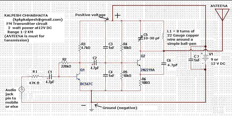
Constructing an FM transmitter for the first time can be challenging due to confusion regarding the necessary components, parts, design, PCB layout, and transmission aspects. An FM transmitter is an electronic device that encodes audio signals into radio frequency waves,...
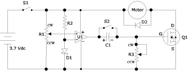
The following circuit illustrates an Airplane Flight Timer Circuit Diagram. Features include switches in the closed position and battery voltage maintained at a safe level. The Airplane Flight Timer Circuit is designed to provide a reliable timing mechanism for monitoring...
The circuit depicted in figure 2-6 and discussed in previous sections serves illustrative purposes only and is not practical in real-world applications. Nevertheless, the fundamental principle involved—the variation in reactance of an oscillator circuit in response to modulating voltage—represents...
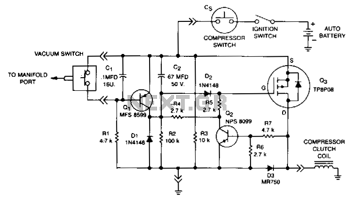
This circuit disables the air conditioner compressor when additional engine power is required. It does so by monitoring the engine vacuum at the intake manifold. If the vacuum drops to 40% of its normal level, the compressor clutch is...
This circuit is a highly stable, harmonic-free, long-range FM transmitter designed to operate within FM frequencies between 88 and 108 MHz. It is capable of covering a range of up to 5 kilometers. The circuit features a stable oscillator...

The power output of most of these circuits is very low because no power amplifier stages were incorporated. The transmitter circuit described here includes an additional RF power amplifier stage, following the oscillator stage, to increase the power output...