
Water-Leak Alarm

The moisture sensor circuit utilizes a PCB foil pattern designed to detect moisture levels in the environment. The core of the sensor is a grid of conductive traces that change resistance based on the presence of moisture. When moisture is detected, the resistance between the conductive traces decreases, allowing current to flow through the circuit.
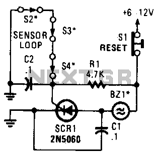
In this configuration, the sensor is connected to a terminal labeled J1. When moisture is detected, it triggers the conduction of CR1, which is likely a transistor or a relay, depending on the design specifics. This conduction activates the buzzer BZ1, providing an audible alert to indicate the presence of moisture.
The design allows for scalability; multiple sensors can be interconnected in parallel. This approach not only increases the effective area of moisture detection but also enables monitoring of different locations simultaneously. Each sensor can be independently wired to the same buzzer or to separate indicators, depending on the desired application.
For optimal performance, it is essential to consider the placement of the sensors, ensuring they are positioned in areas where moisture accumulation is likely. Additionally, the choice of materials for the PCB and the conductive traces should be made to withstand environmental conditions without degrading over time. Proper calibration of the sensors may also be necessary to ensure accurate moisture readings and effective response from the buzzer.
Overall, this moisture sensor design is versatile and can be adapted for various applications, including agricultural monitoring, leak detection, and environmental control systems. If you choose to make your own moisture sensor,; this foil pattern should come in handy. A sensor connected to J1 causes S CR1 to conduct, which sounds buzzer BZ1. The sensor is a PC-board foil pattern grid. Several sensors can be wired in parallel for increased coverage or to monitor several places simultaneously. 🔗 External reference
Related Circuits

Reverse engineered circuit diagram of a popular retail doorknob alarm. It contains a small transmitter and the doorknob acts as an antenna so it will not work on a metal door. When a person comes close to the doorknob...

This circuit for a laser door alarm operates on the principle of laser beam interruption. A low-cost laser pointer serves as the light source. When an object disrupts the laser beam, an alarm is triggered for a few seconds....

A simple two tone water alarm that is light enough to be worn on the upper arm of a sleeper is described. It uses two LMC555 CMOS timer chips followed by a complimentary pair of emitter followers to drive...

The system involves positioning a small magnet near the stalk switch SW1, which is connected to the hand or garments of the individual carrying the bag via a tiny cable. Due to the compact nature of the circuit, it...
A string of three series-connected, normally closed switches is connected across the gate of a silicon-controlled rectifier (SCR). When one switch opens, the SCR is triggered through resistor R1, activating an alarm. The alarm is designed to be of...

This is a simple smoke alarm circuit using a timer IC, the NE555. The circuit operates by illuminating a Light Dependent Resistor (LDR) with a lamp. When smoke obscures the light from the lamp, the resistance of the LDR...