
Preamplifier for magnetic phono cartridges schematics
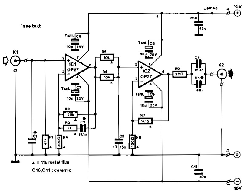
The circuit described consists of two primary amplification stages. The first stage, represented by IC1, operates as a low-noise preamplifier designed to amplify weak signals from a dynamic pick-up. The initial gain of 40 dB allows for effective amplification of low-level signals, which is critical in applications such as audio processing where signal integrity is paramount. The gain reduction to 20 dB at frequencies above 500 Hz indicates a frequency response tailored to minimize noise while maintaining signal fidelity at lower frequencies.
Resistor R3 plays a crucial role in this configuration. Its value is selected to strike a balance between minimizing thermal noise, which can adversely affect signal quality, and ensuring that the operational amplifier (op-amp) does not experience excessive loading at higher frequencies. This careful consideration of resistor value is vital for maintaining the overall performance of the circuit.
Capacitor C2, a polystyrene type, is specified with a tolerance of 1 to 2%. This precision is important in audio applications where variations in capacitance can lead to shifts in frequency response and signal distortion. The choice of polystyrene capacitors is often due to their favorable characteristics, including low dielectric absorption and low noise, which contribute to the high performance of the circuit.
The second stage of the circuit involves IC2, a linear amplifier designed to further boost the output signal from the dynamic pick-up. With a gain of 22 dB, this stage is capable of elevating the output to a more usable level, specifically targeting a line level of 250 mV at 1 kHz. This is particularly important for interfacing with subsequent audio processing equipment, ensuring compatibility and optimal signal levels.
Overall, this circuit design effectively amplifies low-level signals while managing noise and frequency response characteristics, making it suitable for high-fidelity audio applications. The combination of a well-chosen resistor value, a precision capacitor, and a robust linear amplifier stage results in a reliable and high-performance amplification solution.Circuit IC1 provides a do amplification of 40 dB, which drops to about 20 dB when the frequency rises above 500 Hz. To minimize the (resistor) noise and the load of the op amp at higher frequencies, the value of R3 is a compromise.
The associated polystyrene capacitor, C2, should have a tolerance of 1 to 2%. To raise the 2-mV output of the dynamic pick-up to line level at 1 kHz, linear amplifier IC2 has been added. This stage has a gain of 22 dB, so a signal of 250 mV is available at its output. 🔗 External reference
Related Circuits
This is a simple microphone preamplifier circuit designed for use between a microphone and a stereo amplifier. This circuit is compatible with standard home stereo amplifier line, CD, aux, and tape inputs. It can accept both dynamic and electret...
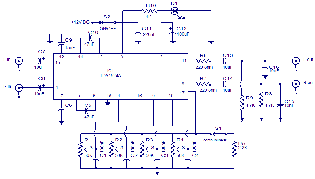
The following circuit illustrates the TDA1524 IC Stereo Preamplifier Circuit Diagram. Features include the ability to control volume, balance, and bass. The TDA1524 is a highly integrated stereo preamplifier IC designed for audio applications. This circuit configuration allows for the...
This timer is intended for individuals seeking to achieve a tan while minimizing excessive exposure to sunlight. A rotary switch adjusts the timer based on six categorized photo-types. A photoresistor modifies the preset time value in relation to sunlight...
Design and dimensioning of active low-pass and high-pass filters using Sallen-Key and multiple feedback topologies. Spice netlist generator. Active low-pass and high-pass filters are essential components in signal processing, allowing specific frequency ranges to pass while attenuating others. The Sallen-Key...
The circuit automatically powers down a computer after Windows has been shut down, preventing users from forgetting to turn off their machines. Upon shutting down Windows, a click occurs after one second, disconnecting the PC from the mains supply....
To complement the 60 Watt MOSFET audio amplifier, a high-quality preamplifier design was necessary. A discrete components topology utilizing ±24V supply rails was selected, with an emphasis on minimizing the transistor count while achieving low noise, very low distortion,...