
Precision Peak voltage detector with a long memory time

This circuit features a basic yet effective design for peak voltage detection in audio signals. The operational amplifier LF353 is chosen for its low noise and high input impedance, which is critical for accurate peak detection. The configuration allows for the detection of both positive and negative peaks in a signal, with the diode D1 ensuring that only the positive peaks are processed during the forward bias condition. The capacitor C1 plays a crucial role in holding the peak voltage level, allowing the circuit to maintain a steady output until the capacitor discharges.
The LM723 serves not only as a voltage regulator in traditional applications but also as a peak level indicator in this configuration. The circuit's design is straightforward, requiring minimal components, which contributes to its ease of assembly and integration into various audio applications. The output can be connected to further processing stages or visual indicators, such as LEDs, to provide a clear representation of the peak levels detected.
This circuit can be particularly useful in audio engineering, sound level monitoring, and other applications where peak signal levels are critical for performance and quality assurance. The simplicity of the design does not compromise its effectiveness, making it an excellent choice for both amateur and professional use in audio signal processing.To check the peak voltage of the signal to change at any time. Measuring with a multimeter will not do it. We recommend this circuit. It may help you. In this circuit is used with a positive signal input, when has negative feedback only. And the inverting input can only get some feedback, when diode D1-1N4148 is forward biased. When we put the input signal is positive, the output voltage of op-amp increases equal to the inverting input signal. When the input is negative, the diode D1 will be reverse bias, the still voltage on the capacitor C1 but it is discharged slowly with an input current of the op-amp IC1 about 10pA. This the circuit checks signal sound level or Circuit Peak Level Indicator by LM723. Usual we often lead IC LM723 or UA723 come to use do, DC voltage Regulator. But for this circuit, build the circuit can check signal sound level with. When see the structure changes the integrated circuit. As a result participate of check volage with then bring apply for this not difficult work extremely. As a result request friends study the work has of the circuit follows a picture be lucky sir. This be the circuit Peak Detector or checks pressure electricity topmost level is easily. Which I uses integrated number circuit LF353 be the integrated circuit op-amp perform measure electricity pressure or, compare with the pressure there.
When see the circuit has already you will like. Because the equipment is a little and build easy. regard circuit idea well yes. 🔗 External reference
Related Circuits
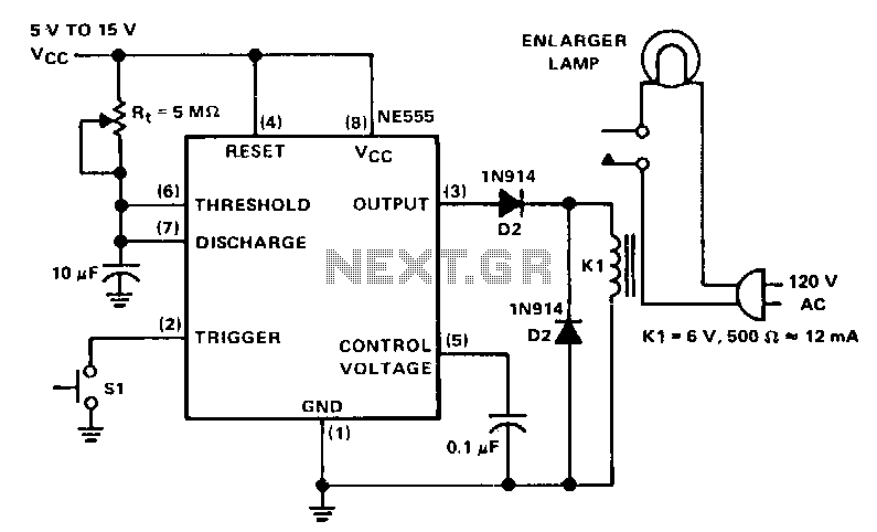
The NE555 circuit functions as a basic one-shot timer, featuring a relay connected between the output and ground. It is triggered by a normally open momentary contact switch, which, when activated, grounds the trigger input at pin 2. This...
Various embodiments of the BB metal detector have been published, and it has been widely described in the press as a new genre. Instead of using a search and a reference oscillator as with BFO, or Tx and Rx...
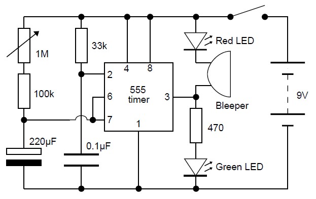
This adjustable analog timer circuit begins timing when it is activated. A green LED illuminates to indicate that the timing is in progress. Upon completion of the set time period, the green LED turns off, a red LED activates,...
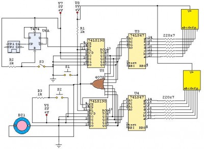
This is a 24-second countdown timer circuit designed for automatic control of electronic loads. The timer circuit utilizes fast 74LS Schottky integrated circuits (ICs). A 24-second countdown begins when switch S3 is off and switch S2 is pressed. Switch...
This circuit utilizes a 1458 dual op-amp to create a radar detector. C1 serves as the radar signal detector. The first op-amp functions as a current-to-voltage converter, while the second op-amp buffers the output to drive the piezo transducer....
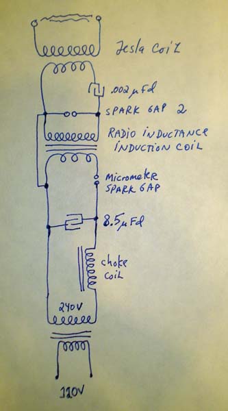
Many individuals assume that spark gap Tesla coils require high voltages, typically ranging from 4 kV to 15 kV or more. However, some interesting experiments can be conducted using as little as 240 V directly. Aside from very low...