
Adjustable Analog Timer Circuit
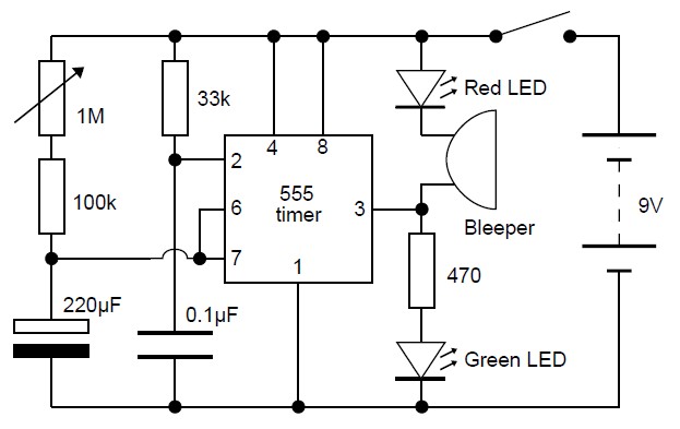
This adjustable analog timer circuit is designed to provide a simple yet effective timing solution for various applications. The circuit is initiated by a switch, which powers the timer and activates the green LED to indicate that timing is underway. The adjustable time period, controlled by a variable resistor, allows for flexibility in timing applications, making it suitable for both recreational and practical uses.
The transition from the green LED to the red LED upon the completion of the set time serves as a clear visual cue, while the buzzer adds an audible alert, enhancing usability. This feature is particularly beneficial in kitchen environments or during activities where a precise time limit is necessary.
The battery monitoring circuit is another practical application, designed to provide a visual representation of the charge level of a 12V lead-acid battery. By using multiple LEDs, this circuit allows users to quickly assess battery status, ensuring timely recharging and maintenance.
The delay circuit, which can be integrated with household lamps, provides a convenient way to maintain illumination for a short duration after the switch is turned off. This feature can enhance safety and convenience in various settings.
The LED flasher circuit demonstrates a basic application of transistor switching, providing an engaging way to learn about electronic components and their functions. The inclusion of a component parts list facilitates easy assembly and experimentation for those new to electronics.
The automatic battery charger circuit exemplifies a practical application of charging technology, ensuring that batteries are maintained at optimal levels. The traffic light controller circuit serves an educational purpose, allowing children to learn about traffic signals through hands-on experience with electronics.
Overall, these circuits reflect a variety of foundational electronic concepts and applications, making them suitable for educational purposes, hobby projects, and practical implementations in everyday life.This Adjustable Analog Timer circuit starts timing when switched on. A green LED lights to show that timing is in progress. When the time period is over the green LED turns off, a red LED turns on and a bleeper sounds. The time period is set by a variable resistor and it can be adjusted from 1 to 10 minutes (approximately). It could be used to set a time limit when playing games or as an egg-timer in the kitchen. This is a very simple adjustable analog timer circuit diagram. You can build this circuit just for fun, for newbie project or may be. , this circuit could be used to set a time limit when playing games or as an egg-timer in the kitchen. The circuit will start timing when switched on. The green LED. This circuit is designed to monitor the level of power capacity at 12V Lead-Acid battery. Battery power level will be indicated by LEDs. This easy circuit makes it possible to monitor the charging process to a higher level. Final adjustsments are simple and easy and the only device required is a digital voltmeter for the. Following is a circuit you can use to delay an electronic device to be disabled. For example, you can connect this circuit to the lamp in your room. When you turn off the lamp with a switch on the circuit, the lamp will remain lit in a certain period of time, before the lamp really.
The following is LED Flasher circuit which use 2 transistors for LED switching. The circuit works similar to flip-flop operation. Component Parts List: R1 = 10M ohm R2 = 1K - 100K ohm R3 = 470 ohm C1 = 0. 47 F - 10 F/25V D1 = 1N914 Q1 = 2N3904 Q2 = 2N3906 Led = High Brightness. This is the diagram of Automatic 9V Battery Charger circuit. The circuit designed by Jan Hamer, translated by Tony Van Roon dan republished in this circuit diagram site. The circuit details are based on european standards. 120E, 150E, etc. The `E` just stands for Ohms so 120 ohm, 150 ohm. The original circuit specified the. Here the simple traffic light controller which is could be used to educate kids rudiments of traffic light guidelines.
The circuit utilizes easily available electronic parts. It generally consists of rectifier diodes (1N4001), a 5V regulator 7805, two timers circuit using IC 555, two relays (5V, single-changeover), three 15W, 230V light bulbs and also several. 🔗 External reference
Related Circuits
How many individuals have experienced legitimate issues with the 555 timer? It can be inferred that these problems often involve the reset line, specifically pin 4, which must be set high before operation. The 555 timer IC is a versatile...
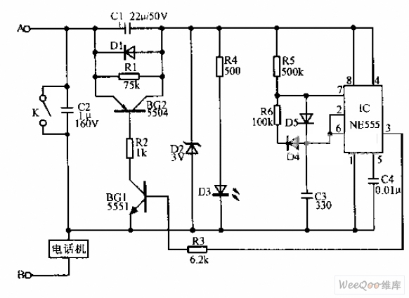
A simple telephone time lock circuit is depicted in the provided diagram. In this circuit, BG1 and BG2 function as electronic switches that are controlled by the IC NE555. When the telephone is on-hook, the DC resistance of the...
A newer version of this circuit board is available. Rev 4 includes a faster CPU, more memory, more I/O, and an optional LCD. It is recommended to use Rev 4 for new projects. Although the older board is no...
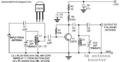
The coil L2 is tapped at the first turn from the ground lead side and is similar to coil L1, but consists of only three turns. The pin configuration of the transistor 2SC2570 is illustrated in the FM antenna...
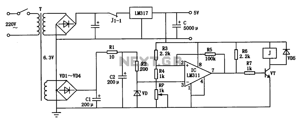
The circuit depicted can be utilized to operate at a voltage of +5V for Single Board Computer (SBC) power, preventing damage caused by over-voltage from the power supply throughout the SBC. This circuit serves as a protective mechanism for Single...
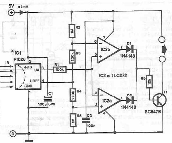
This infrared detector circuit utilizes the PID20 integrated circuit manufactured by Siemens, which converts thermal radiation into electrical impulses. It includes an operational amplifier and several electronic components. The output signal at pin 3 is compared to a reference...
Warning: include(partials/cookie-banner.php): Failed to open stream: Permission denied in /var/www/html/nextgr/view-circuit.php on line 713
Warning: include(): Failed opening 'partials/cookie-banner.php' for inclusion (include_path='.:/usr/share/php') in /var/www/html/nextgr/view-circuit.php on line 713