
economy radar detector
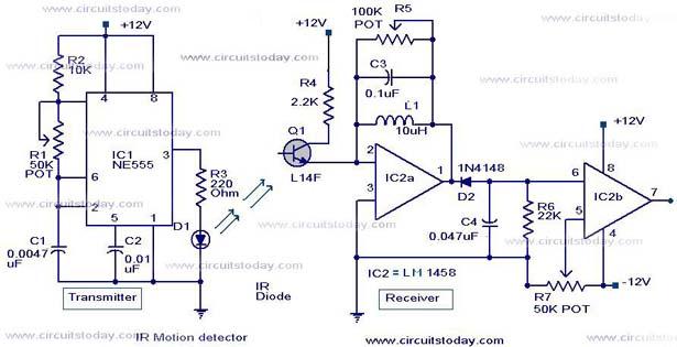
The radar detector circuit employs a 1458 dual operational amplifier (op-amp) to effectively detect radar signals. The first op-amp is configured as a current-to-voltage converter, which translates the incoming radar signal current into a corresponding voltage. This conversion is critical for the subsequent processing of the signal. The output from this op-amp is then fed into the second op-amp, which is configured as a buffer. The buffering stage is essential as it ensures that the output can drive a piezo transducer without loading down the previous stage, thus maintaining signal integrity.
The component C1 plays a pivotal role as the radar signal detector, and its performance can be influenced by the physical characteristics of the leads connected to it. The length of these leads is crucial; for optimal performance with typical road radar systems, they should be approximately 0.5 to 0.6 inches long. This dimension helps to tune the circuit's response to the radar frequencies of interest while minimizing interference from background noise.
Resistor R5 is a critical component for setting the switching threshold of the second op-amp. Proper adjustment of R5 allows the circuit to distinguish between actual radar signals and background noise. Initially, the threshold is set so that the circuit just begins to trigger on background noise, and then it is slightly adjusted to prevent false triggering. This careful calibration ensures that the radar detector operates effectively in different environments and under varying conditions.
Overall, this radar detector circuit demonstrates a straightforward yet effective design utilizing a dual op-amp configuration, with key components selected to optimize performance for real-world applications.This circuit uses a 1458 dual op-amp to form a radar detector. C1 is the detector of the radar signal. The first op-amp forms a current-to-voltage converter and the second op-amp buffers the output to drive the piezo transducer. R5 sets the switching threshold of the second op-amp; normally it is adjusted so that the circuit barely triggers on bac
kground noise, then it`s backed off a bit. The response of the circuit may be tuned by adjusting the length of the leads on C1. For typical road-radar systems, the input capacitor`s leads should be about 0. 5 to 0. 6 inches 🔗 External reference
Related Circuits
This project has not been called a GOLD detector as this name has been left for the more complex detectors that actually discriminate between gold and other metals. There is an enormous difference between detecting gold and ordinary metals...
A straightforward smoke detector circuit has been presented through a schematic diagram, which can be easily constructed and installed in an area for essential detection purposes. The circuit utilizes the versatile FIGARO TGS 813 gas sensor as the primary...
Infrared (IR) Motion Detector Circuit featuring a motion detector alarm and an infrared sensor. The circuit diagram and its operation are provided in detail. The infrared (IR) motion detector circuit is designed to detect motion within a specified range and...
A Coil Coupled Operation Metal Detector made from readily obtainable components and using an ordinary medium receiver as a detector. The metal detector shown here may well represent a new genre. At any rate, after some exposure, it is...
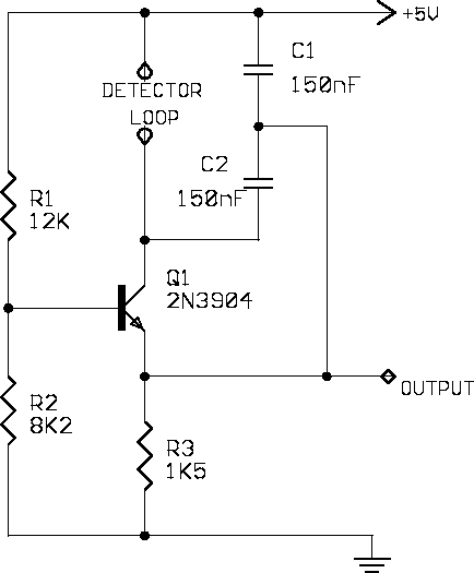
A simple single-transistor Colpitts oscillator is depicted in the schematic. When a vehicle passes over the loop, the inductance decreases, resulting in an increase in the oscillator frequency. A microprocessor measures the oscillator frequency and takes appropriate actions based...
Cellular phone detector circuit schematic using common electronic parts The cellular phone detector circuit is designed to identify the presence of a cellular phone within a specified range. This circuit utilizes basic electronic components, making it accessible for hobbyists and...