
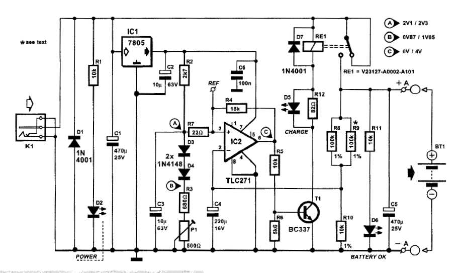
Programmable Current and Voltage Regulator for Battery Charger
The programmable current and voltage regulator circuit is designed to provide precise control over output voltage and current levels. This circuit typically employs an integrated voltage regulator, which can be adjusted to output a desired voltage level, while also incorporating an external current limiting feature to protect connected loads from excessive current.
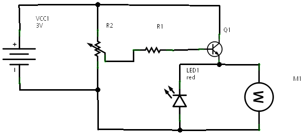
The voltage regulator operates by maintaining a stable output voltage despite variations in input voltage or load conditions. The use of a variable resistor, designated as R2, allows for fine-tuning of the output voltage. By adjusting R2, users can set the desired voltage level according to the requirements of the application.
In addition to the voltage regulation, the current limiting aspect of the circuit is crucial for safeguarding sensitive components. This feature can be implemented using a current sensing resistor placed in series with the load. When the current exceeds a predefined threshold, the circuit can reduce the output voltage or shut down completely to prevent damage.
The overall design may also include additional components such as capacitors for stability, diodes for reverse polarity protection, and transistors for amplification or switching purposes, depending on the specific requirements of the application. Proper layout and thermal management are essential to ensure reliable operation, especially in high-current scenarios.
This circuit configuration is widely used in power supply designs, battery chargers, and various electronic devices requiring stable power delivery with adjustable parameters. Understanding the interplay between the voltage regulator, current sensing, and variable resistance is key to optimizing performance and reliability in practical implementations.This is a programmable current and voltage regulator circuit. It consist of a voltage regulator with external current limitation. The variable resistor R2 is.. 🔗 External reference
Related Circuits
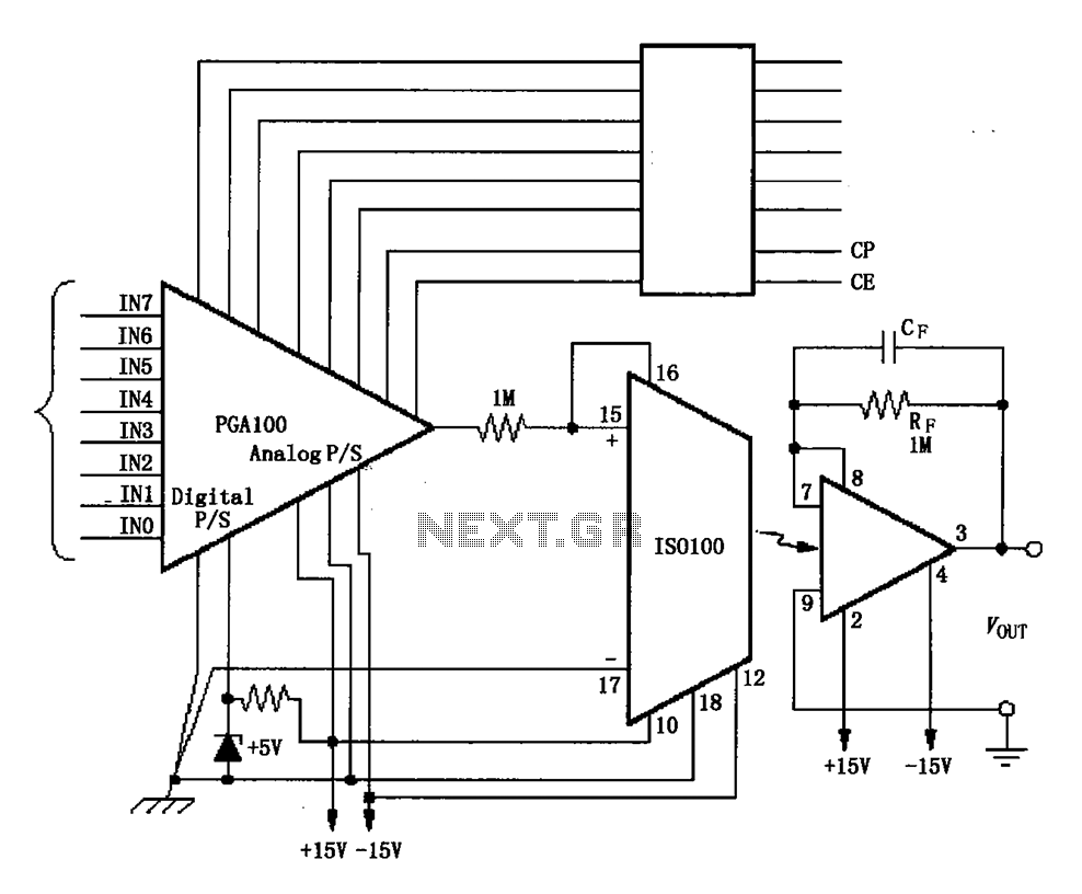
The ISO100 multichannel data acquisition system comprises a programmable gain amplifier isolated by an optocoupler, a programmable amplifier (PGA100), and an isolation amplifier (ISO100). The optocoupler selects three channels and is coupled to the programmable gain amplifier, which can...
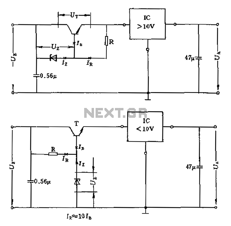
The voltage equation Ue = Ut + Ur + Ua indicates that the transistor voltage Ut will determine the maximum output voltage Ua. Additionally, Ur must be 2V. The voltage regulator's voltage value depends on the selection of Uz....
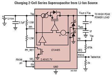
The LTC4425 is a constant-current/constant-voltage linear charger designed to charge a two-cell supercapacitor stack from a Li-Ion/Polymer battery, a USB port, or a current-limited supply ranging from 2.7V to 5.5V. This component functions as an ideal diode with a...
There are two regulator circuits that utilize the L200 integrated circuit from SGS-Thomson to regulate voltage and current. In circuit Fig. 1, the output voltage can be adjusted using the variable resistor RV1. In Fig. 2, both output voltage...
An automatic battery charger initiates the charging process when the battery voltage falls below a specified threshold and ceases charging once the voltage exceeds a predetermined maximum value. The setup is straightforward; simply connect two alligator clips to the...
In a prior post titled "Timing is Everything," the application of PWM (Pulse Width Modulation) signals for controlling devices such as LEDs was discussed. This technique is particularly beneficial when working with digital devices, including microchips and microcontrollers, which...