
Programmable Sound Generator

The AY-3-8910/8912 Programmable Sound Generator (PSG) operates as a versatile audio synthesis device, primarily utilized in microprocessor-controlled applications to generate sound effects and music. Its architecture is based on memory-mapped I/O, allowing for seamless communication between the microprocessor and the PSG through 16 dedicated registers. These registers facilitate both command issuance and status reading, enabling the microprocessor to manage sound generation effectively without dedicating extensive processing resources to audio tasks.
The internal structure of the AY-3-8910/8912 includes several key components essential for sound production. The Tone Generators are responsible for producing square wave tones across three channels (A, B, and C), with each channel capable of generating distinct frequencies. The Noise Generator contributes a pseudo-random noise signal, which can be modulated for various sound effects. The Mixers combine the outputs from the Tone Generators and the Noise Generator, allowing for complex soundscapes to be created by mixing different audio signals.
Amplitude Control and the Envelope Generator work together to shape the sound output. The Amplitude Control block can provide either fixed or variable amplitude signals to the Digital-to-Analog Converters (D/A Converters). The Envelope Generator modulates the amplitude over time, allowing for dynamic sound effects such as fades and crescendos.
Additionally, the AY-3-8910/8912 features two I/O Ports (A and B), which facilitate external interfacing with other devices or components, enhancing the PSG's functionality beyond sound generation. These TTL-compatible ports enable data transfer without interfering with the PSG's core audio functions.
The operational integrity of the PSG relies on the Bus Control Decode block, which interprets bus control signals from the microprocessor. This block ensures that the correct operations—such as reading from or writing to the PSG's registers—are executed based on the current bus state. The timing of these operations is critical and is detailed in the electrical specifications, ensuring that the system operates within the defined parameters for reliable performance.
Overall, the AY-3-8910/8912 PSG represents a sophisticated solution for sound synthesis in digital systems, providing a range of features that enable high-quality audio generation while minimizing the load on the main processor.The AY-3-8910/8912 is a register oriented Programmable Sound Generator (PSG). Communication between the processor and the PSG is based on the concept of memory-mapped I/O. Control commands are issued to the PSG by writing to 16 memory-mapped registers. Each of the 16 registers within the PSG is also readable so that the microprocessor can determine, as necessary, present states or stored data values. All functions of the PSG are controlled through its 16 registers which once programmed, generate and sustain thesounds, thus freeing the system processor for other tasks.
Conditioning of the Register Address Latch/Decoder and the Bidirectional Buffers to recognize the bus function required (inactive, latch address, write data, or read data) is accomplished by the Bus Control Decode block. The function of each of the 16 PSG registers and the data flow of each register’s contents are shown in context in Fig.
2 and explained in detail in Section 3, Operation”. For reference purposes, the Register Array details are reproduced in Fig. 3. 2.1.2 SOUND GENERATING BLOCKS The basic blocks in the PSG which produce the programmed sounds include: Tone Generators Noise Generator Mixers Amplitude Control Envelope Generator D/A Converters produce the basic square wave tone frequencies for each channel (A,B,C) produces a frequency modulated pseudo random pulse width square wave output. combine the outputs of the Tone Generators and the Noise Generator. One for each channel (A,B,C). provides the D/A Converters with either a fixed or variable amplitude pattern. The fixed amplitude is under‘ direct ‘CPU control; the variable amplitude is accomplished by using the output of the Envelope Generator.
produces an envelope pattern which can be used to amplitude modulate the output of each Mixer. the three D/A Converters each produce up to a 16 level output signal as determined by the Amplitude Control. 2.1.3 I/O PORTS Two additional blocks are shown in the PSG Block Diagram which have nothing directly to do with the production of sound-these are the two I/O Ports (A and B).
Since virtually all uses of microprocessor-based sound. would require interfacing between the outside world and the processor, this facility has been included in the PSG. Data to/from the CPU bus may be read/written to either of two 8-bit I/O Ports without affecting any other function of the PSG.
The I/O Ports are TTL-compatible and are provided with internal pull-ups on each pin. Both Ports are available on the AY-3-8910; only I/O Port A is available on the AY-3-8912. Since the PSG functions are controlled by commands from the Bus Timing system processor, the common data/address bus (DA7--DAO) requires definition as to its function at any particular time. This is accomplished by the processor issuing bus control signals, previously described, defining the state of the bus; the PSG then decodes these signals to perform the requested task.
The conditioning of these bus control signals by the processor is the same as if the processor were interacting with RAM: (1) the processor outputs a memory address; and (2) the processor either outputs or inputs data to/from the memory. The memory” in this case is the PSG’s array of 16 read/write control registers. The timing relationships in issuing the bus control signals relative to the data or address signals on the bus are reviewed in general in the following section, and in detail in Section 7, Electrical Specifications.
🔗 External reference
Related Circuits
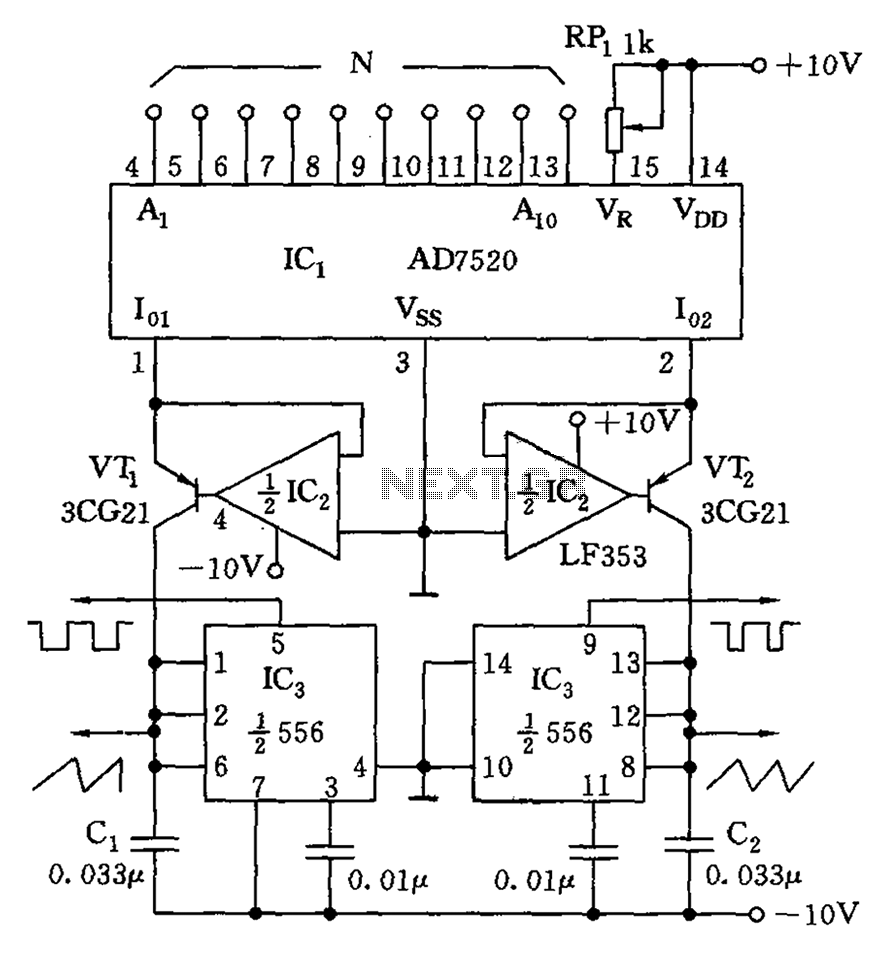
As shown in the figure, the AD7520 is a CMOS type integrated circuit Digital-to-Analog Converter (DAC) featuring 10 channels. It can provide 10 N-bit digital outputs that are proportional to the input current Io1, as well as outputs that...
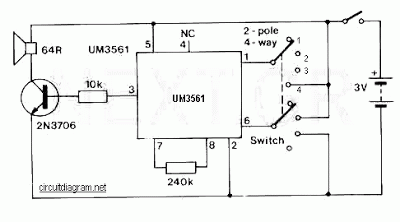
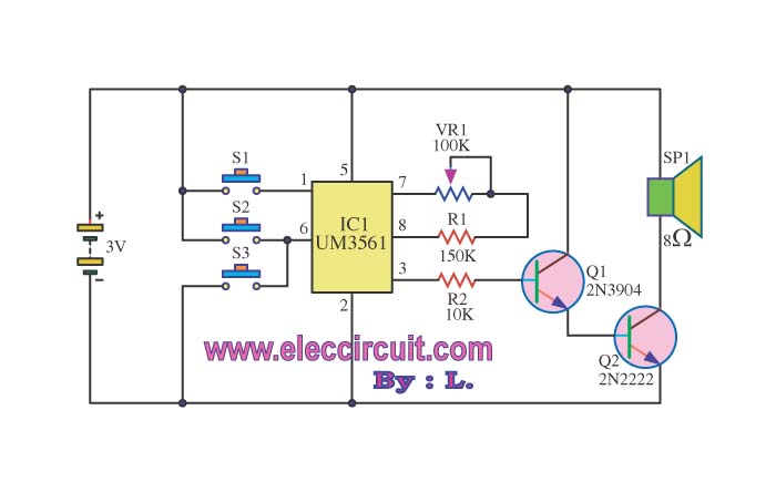
This is a straightforward sound effect generator based on the single sound generator chip UM3561. The UM3561 can produce four types of sound effects. Its basic operation involves generating a sound signal, which is then delivered to a 2N3706...

A simple yet effective circuit to generate a POTS-compatible ringing voltage can be constructed using National Semiconductor's LM4871 audio amplifier IC along with a dozen passive components. This circuit produces a sine-wave output of 1 W at approximately 70...
The basic idea comes from the AN592 Microchip application note: "Frequency counter using PIC16C5x". where you may find a simple software which implements a frequency counter using a PIC microcontroller. I wrote a specifically designed software to improve the...
This invention is a back EMF permanent electromagnetic motor generator and method that utilizes a regauging process to capture available electromagnetic energy within the system. The device consists of a rotor equipped with magnets of the same polarity, a...
The circuit operates using a UM3516 integrated circuit (IC1), which is designed to generate sound. The output sound is produced at pins 7 and 8 of IC1, and the components R1 and VR1 are utilized to control the frequency...