
Programmable frequency meter

The frequency counter circuit is based on the Microchip PIC16C5x microcontroller, which is programmed to measure frequencies and display the results on an LCD screen. The microcontroller handles the main functionalities, including frequency measurement, data processing, and user interface management through an operating menu. The software is tailored to enhance counter resolution and to facilitate the handling of intermediate frequency (IF) values.
An essential component of the circuit is the input signal amplifier, which is designed to elevate the input signal from a range of 200-300 mV peak-to-peak to approximately 3 V peak-to-peak. This amplification is crucial for ensuring that the signal is adequately processed by the RA4 pin of the PIC microcontroller. The amplifier stage utilizes a 2N2369 transistor configured in a common emitter arrangement. A small inductance is connected in series with the collector load to optimize frequency response, allowing the circuit to effectively amplify signals in the range of 100 KHz to 50 MHz. The lower frequency limit is determined by the capacitor C10, which sets the cutoff frequency of the amplifier.
The design includes a feedback resistor, R8, selected to yield a collector voltage of approximately 1.6-1.8 V. This voltage is necessary to ensure proper triggering of the PIC's input gate. It is advisable to measure this voltage after assembly to confirm that the amplifier is functioning correctly before installing the PIC into its socket.
For time base generation, a 4 MHz parallel resonant crystal oscillator is employed. This crystal serves as the frequency reference for the measurement system. The capacitance value of C9 can be adjusted to fine-tune the oscillation frequency, and it is suggested to use a trimmer capacitor for precise calibration. The frequency stability is typically within a tolerance of 50 parts per million (ppm).
Powering the circuit is managed by a 78L05 voltage regulator, which supplies the necessary 5 V for the microcontroller and other components, accommodating a current of up to 15 mA. If a backlit LCD is used, a 7805 regulator should be implemented instead, as it can handle up to 60 mA without overheating. The circuit features a 16-pin connector, with pins 15 and 16 designated for powering the LCD backlight. The supply voltage for the entire system should be maintained within the range of 8-12 volts, with R9 used as a variable resistor to adjust the brightness of the LCD display.The basic idea comes from the AN592 Microchip application note: "Frequency counter using PIC16C5x". where you may find a simple software wich implements a frequency counter using a PIC microcontroller.I wrote a specifically designed software to improve the counter resolution, to handle the IF mode and value by means of an operating menu, to decode and edit the read frequency on an LCD display.
The result was a simple and effective device, equipped with a free software available to those who could be interested. The electrical schematic is very simple, given that most of the functions are implemented by the microprocessor. It was needed only an amplifier stage to raise the input signal level from 200-300 mV p.p. to about 3 volts p.p., so as to drive correctly the RA4 (pin 3) triggered gate of the PIC. I implemented a common emitter amplifier using a 2N2369 transistor, with a small inductance series connected to the collector load, so as to improve the frequency response at the high frequencies.
So it was obtained a suitable gain from 100 KHz up to about 50 MHz, the lower limit being forced only by the C10 capacitor. The R8 value is chosen so as to obtain about 1,6-1,8 V on the transistor collector, such a value is necessary to drive correctly the PIC gate, and you may verify this voltage after completing the assembly, and before inserting the PIC on its socket.
The time base is provided from a 4 MHz, parallel resonant, microprocessor crystal, if you have at your disposal a professiona l frequency meter, you may tune accurately the frequency by adjusting the value of C9, which could also be replaced by a little plastic trimmer, otherwise the reading will be in any case within the quartz tolerance (typically 50 p.p.m. max). The 78L05 regulator is well suited to feed the 15 mA required, however if you want to employ a back-lighted LCD module, it will be necessary to replace it with a 7805 model, capable to supply about 60 mA without excessive heating.
On the 16 pin connector two pins are provided (15, 16) to drive the LCD LED panel. The supply voltage should be in the 8-12 volts range, and you may control the display brightness by turning the R9 trimmer, the maximum value being obtained with the cursor completely turned toward the ground. 🔗 External reference
Related Circuits
This project was designed and constructed as enhancement to the 0-30V Stabilized Power Supply Project with the DIY electronics hobbyist in mind. The circuit uses a single PIC Microchip to perform the Voltage, Current and Temperature conversions and display...
A Wien-bridge oscillator can be made variable by utilizing two frequency-determining components that are adjusted simultaneously with high tracking accuracy. However, high-quality tracking potentiometers or variable capacitors are often costly and challenging to procure. To circumvent the need for...
One of the goals of Movable Party is to provide an interactive experience for audiences and participants. Power will be generated from a hub motor attached to the rear wheel of each bike, with the speed of the rear...
This 1 kHz linear-scale analog frequency meter circuit utilizes the 555 timer as a pulse counter. The frequency is displayed on meter M1, a 1 mA meter, which can be calibrated to indicate readings from 0 to 1 kHz. The...
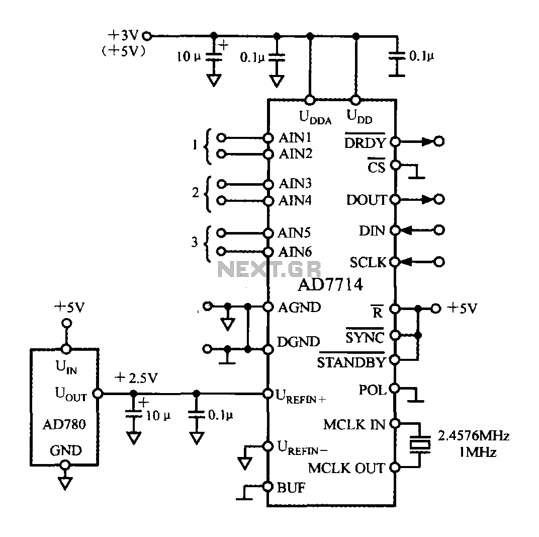
The typical application circuit for the AD7714 is illustrated in the accompanying figure. The UDD and UDDA terminals of the AD7714 can be connected to either a +3V or +5V power supply. The analog inputs are arranged as three...
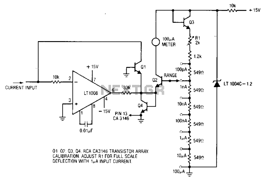
The ammeter measures currents ranging from 100 pA to 100 µA without the need for costly high-value resistors. Accuracy at 100 µA is constrained by the offset voltage between Q1 and Q2, while at 100 pA, it is limited...