
John C. BEDINI free energy Motor/Generator

The back EMF permanent electromagnetic motor generator is designed to optimize energy capture through its innovative regauging process. The rotor's magnets, arranged with the same polarity, interact with the stator's magnetized pole pieces, facilitating the generation of back EMF. The timing wheel and Hall Effect pickup switch play crucial roles in synchronizing the rotor's motion with the magnetic field changes, enhancing the efficiency of energy capture.
The stator's dual-bar configuration, each wrapped with conductive coils, allows for effective electromagnetic induction. As the rotor spins, it induces a current in the output coils, which is then rectified by the recovery diode. This process transforms the generated AC current into usable DC power, which can be utilized to recharge batteries or power external devices.
The regauging effect is particularly significant; by reversing the magnetic field in the pole pieces, the device collapses the flux fields, allowing for the efficient capture of back EMF energy that would otherwise be lost. This innovative approach not only maximizes energy recovery but also minimizes the need for continuous external power input, addressing one of the primary limitations of traditional EMF motors.
The design emphasizes the importance of minimizing internal losses, which is a common challenge in electromagnetic systems. By utilizing advanced materials and optimizing the geometry of the stator and rotor, the efficiency of the motor generator can be significantly improved. The potential for high COP ratings indicates that this device could represent a significant advancement in electromagnetic motor technology, providing a more sustainable and efficient means of energy generation and utilization.This invention is a back EMF permanent electromagnetic motor generator and method using a regauging process for capturing available electromagnetic energy in the system. The device is comprised of a rotor with magnets of the same polarity; a timing wheel in apposition to a magnetic Hall Effect pickup switch semiconductor; and a stator
comprised of two bars connected by a permanent magnet with magnetized pole pieces at one end of each bar. There are input and output coils created by wrapping each bar with a conducting material such as copper wire.
Energy from the output coils is transferred to a recovery rectifier or diode. The magnets of the rotor, which is located on a shaft along with the timing wheel, are in apposition to the magnetized pole pieces of the two bars. The invention works through a process of regauging, that is, the flux fields created by the coils is collapsed because of a reversal of the magnetic field in the magnetized pole pieces thus allowing the capture of available back EMP energy.
Additional available energy may be captured and used to re-energize the battery, and/or sent in another direction to be used as work. As an alternative, the available back EMF energy may be dissipated into the system. The invention relates generally to the capturing of electromagnetic energy using a method and device to create back EMF (electromagnetic force) and re-phasing of the back EMF to recycle and capture the available back EMF energy.
Back EMF is also referred to as regauging and may be defined as energy created by the magnetic field from coils, and only by coils, and not by magnets. Operation of a normal magnetic motor has the rotor pole attracting the stator pole, resulting in the generation of power from the magnets to the rotor and flywheel.
During this phase, energy flows from the magnetics to the rotor/flywheel and is stored in the increased rotation. A rotor pole leaving a stator pole and creating a condition of drag-back results in power having to be put back into the magnetic section by the rotor and flywheel to forcibly overcome the drag-back.
In a perfect, friction-free motor, the net force field is therefore referred to as most conservative. In other words, a most conservative EMF motor has maximum efficiency. Without extra energy continually fed to the motor, no net work can be done by the magnetic field, since half the time the magnetic field adds energy to the load (the rotor and flywheel) and the other half of the time it subtracts energy back from the load (the rotor and flywheel).
Therefore the total net energy output is zero in any such rotary process without additional energy input. To use a present day magnetic motor, continuous energy must be input into the motor to overcome drag-back and to power the motor and its load.
Present EMF motors and generators all use such conservative fields and therefore, have internal losses. Hence, it is necessary to continually input all of the energy that the motor outputs to the load, plus more energy to cover losses inside the motor itself.
EMF motors are rated for efficiency and performance by how much energy input into the motor actually results in output energy to the load. Normally, the Coefficient of Performance (COP) rating is used as a measure of efficiency. The COP is the actual output energy going into the load and powering it, divided by the energy that must be input into the device with its load.
COP is the power out into the load, divided by the power input into the motor/load combination. If there were zero internal losses in a motor, that "perfect" motor would have a coefficient of performance (COP) equal to 1. 0. That is, all energy input into the motor would be output by the motor directly into the load, and none of the input energy would be lost or dissipated in the motor itself.
In magnetic motor generators presently in use, however, due to friction and design flaws, 🔗 External reference
Related Circuits
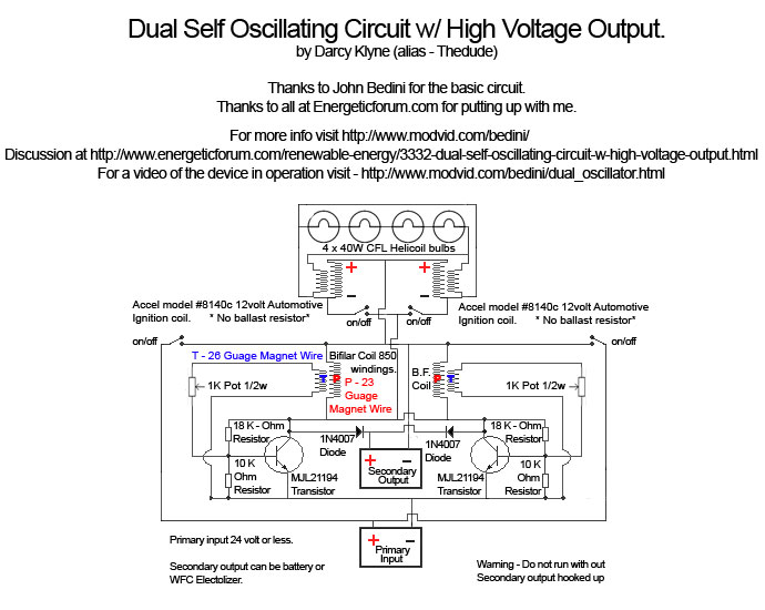
A Tesla pancake coil is connected in series with a bifilar wound coil to generate resonance and a sharp gradient discharge, which creates a vacuum flux. The circuit operates with a CFL at approximately 0.07 amps and 12.42 volts,...
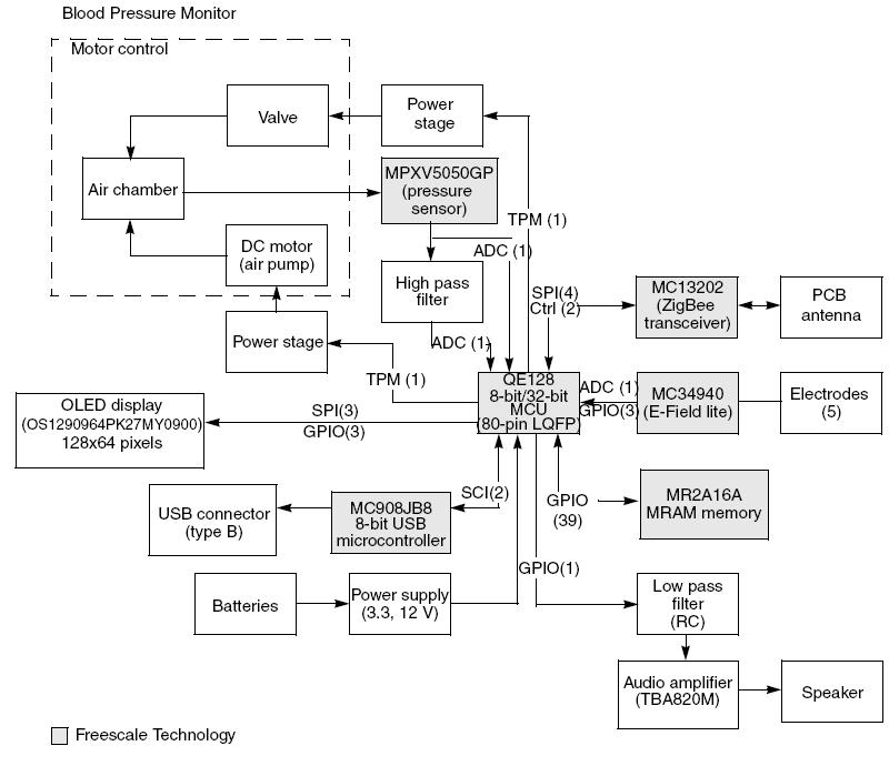
This article demonstrates the implementation of a system capable of measuring arterial blood pressure values. The arterial blood pressure measurement system typically consists of several key components, including sensors, signal processing units, and display interfaces. The primary sensor used in...
Some relays may become warm if they remain energized for an extended period. The circuit presented here will actuate the relay as before but will reduce the hold current through the relay coil by approximately 50%, significantly decreasing heat...
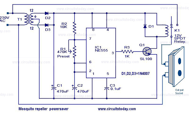
The circuit diagram of a mosquito repellent power saver circuit is provided along with a detailed explanation. The mosquito repellent power saver circuit is designed to efficiently operate a mosquito repellent device while minimizing energy consumption. This circuit typically integrates...
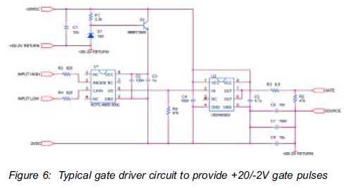
The silicon carbide (SiC) MOSFET offers notable advantages, including a straightforward drive circuit. It possesses unique characteristics that render it a superior switching device in comparison to traditional options. The silicon carbide MOSFET is a type of field-effect transistor that...
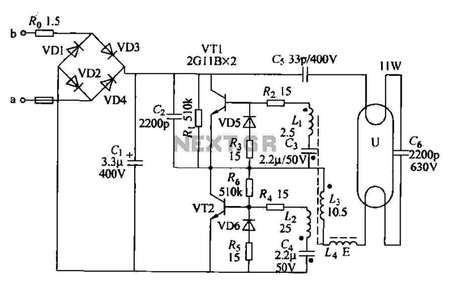
Energy-saving lamps are categorized into self-ballasted compact types and single-ended structures. They can also be classified based on appearance into various forms such as double-tube, four-tube, six-tube types, and others. The lifespan of energy-saving lamps is approximately ten times...