
Programmable Unijunction Transistor (PUT) Flasher Circuit
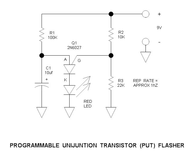
The circuit utilizes a programmable unijunction transistor (PUT) to demonstrate its operation as an oscillator. The PUT, which is a three-terminal device, is capable of generating a pulse output when a specific threshold voltage is exceeded. This characteristic makes it suitable for applications such as timing circuits and flashers.
In the schematic, the PUT is connected in a basic flasher configuration. The circuit typically includes a resistor-capacitor (RC) network that determines the oscillation frequency. The capacitor charges through the resistor until the voltage across it reaches the gate trigger voltage of the PUT. At this point, the PUT turns on, allowing current to flow through the load (often an LED or a small bulb) and discharging the capacitor. Once the capacitor discharges below a certain threshold, the PUT turns off, and the cycle repeats.
Key components in the circuit include the PUT, a resistor (R) for current limiting, a capacitor (C) for timing, and a load (such as an LED). The values of R and C can be adjusted to modify the flashing rate of the output. The circuit can be easily assembled on a proto-board, allowing for rapid prototyping and experimentation.
Proper attention should be given to the power supply voltage and the ratings of the components to ensure reliable operation. The circuit can serve as an educational tool for understanding the behavior of programmable unijunction transistors in oscillating applications.This is simple circuit that illustrates the function of the programmable unijunction transistor. It may be quickly wired on a proto-board. PUT Flasher Spec..
Related Circuits
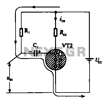 Multivibrator oscillation circuit
It is seen from the ring, when vri off, 0 [2 is turned on, the current through RJ, Ci: When VT1 conduction, charging Cl start discharge. Then give cl inverting charge, I voltage becomes positive, vri turned on. So uc: close O, so that VT2 base electrode becomes negative,...
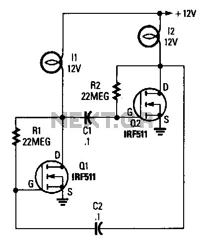 Lamp-flasher
The circuit is built around two power FETs, which are configured as a simple astable multivibrator to alternately switch the two lamps on and off. The rc values given sets the flash rate to about 1/3 Hz. By varying either the resistor or capacitor values, ...
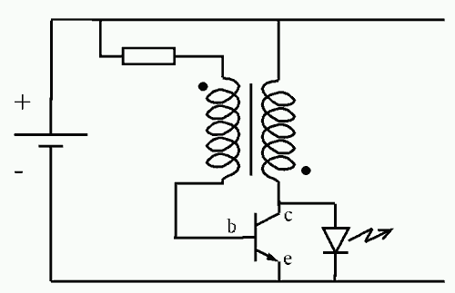
 TV remote control blocker/jammer circuit diagram
Just point this small device at the TV and the remote gets jammed. The circuit is self explanatory. 555 is wired as an astable multivibrator for a frequency of nearly 38 kHz. This is the frequency at which most of the modern TVs receive the IR beam. The transistor acts...
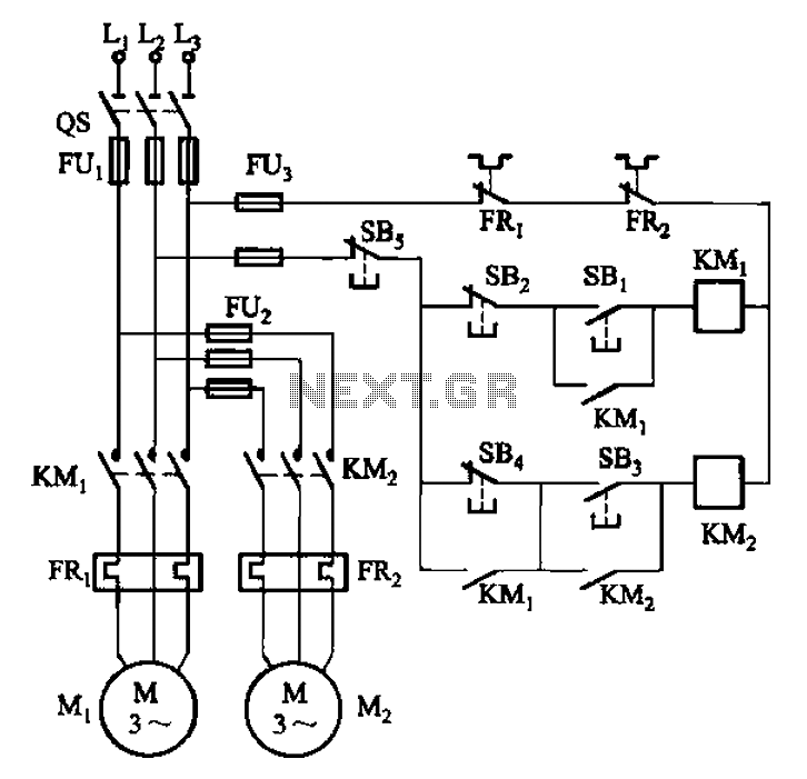 Host stall after stall to auxiliary control circuit
Circuit shown in Figure 3-84. Be seen by the two electric motors can be started separately. But only when you press Host (Ml) of the stop button SBz (after contact KMi release)
 10 Dancing LEDs ElectronicCircuit Based On The LM358 IC
The following circuit shows about 10 Dancing LEDs Electronic Circuit Diagram. This circuit based on the LM358 IC. Features: IC1A amplifies about ..