
project turing machine
The General Purpose Input/Output (GPIO) pins on the Raspberry Pi provide versatile capabilities for interfacing with various electronic components. Each GPIO pin can be configured as either an input or an output, facilitating a wide range of applications from simple LED control to complex sensor integration. The Raspberry Pi features a total of 26 pins, including power supply pins for 3.3V and 5V, ground connections, and dedicated GPIO pins.
In practical applications, the GPIO pins are often used in conjunction with a breadboard, which simplifies circuit construction. The breadboard's layout, marked with red and blue lines for power and ground rails, allows for easy connection of components. Each segment of holes on the breadboard is interconnected, enabling multiple components to share connections without additional wiring.
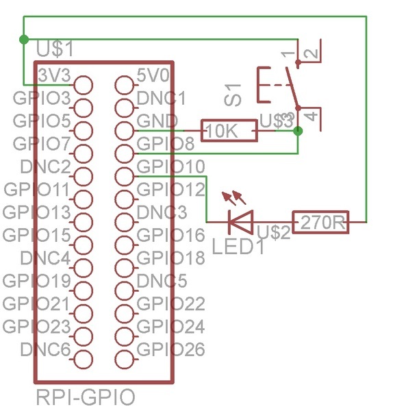
For example, when configuring GPIO10 as an output, it can control an LED. The LED's anode connects to the 3.3V rail through a resistor, while the cathode connects to GPIO10. When GPIO10 is set low, the LED is activated, illuminating the circuit. Conversely, setting GPIO10 high deactivates the LED. Similarly, GPIO8 can be configured as an input to read the state of a pushbutton switch. When the switch is pressed, GPIO8 reads a high state, allowing the system to respond accordingly.
Programming these interactions involves writing scripts in Python, utilizing the RPi.GPIO library to manage GPIO configurations and states. The correct installation of this library is essential for executing control scripts. The code can be executed from the terminal, enabling real-time interaction with the hardware.
In advanced applications requiring more I/O capabilities, the PCF8574AN I²C Bus I/O expander can be employed. This chip expands the number of available GPIO pins by allowing the Raspberry Pi to communicate with multiple devices over a serial bus. The integration of the PCF8574AN involves connecting its SDA and SCL pins to the corresponding pins on the Raspberry Pi, establishing a communication link. The I²C protocol facilitates the addressing of multiple slave devices, making it ideal for projects with numerous inputs and outputs.
In summary, the GPIO functionality of the Raspberry Pi, combined with components such as breadboards, LEDs, switches, and I²C expanders like the PCF8574AN, provides a robust platform for developing diverse electronic projects. The combination of hardware configuration and software control enables engineers and hobbyists to create innovative solutions in various applications.GPIO, as may have been explained in other tutorials, stands for General Purpose Input/Output and a GPIO pin can be set high (taking the value 1) by connecting it to a voltage supply, or set low (taking the value 0) by connecting it to ground. The Raspberry Pi can set the pin to take either value and treat it as an output, or it can detect the value of the pin and treat it as an input.
There are twenty-six pins in total: three power supply pins, 3V3 (3. 3V), 5V0 (5. 0V) and GND (0V); 6 DNC (do not connect) pins; and seventeen GPIO pins. Some of these seventeen pins have alternative functions as well, but we won`t dwell on those now. A breadboard has several key features. It has red and blue lines which demarcate the holes belonging to the supply voltage rails (which will be 3. 3V for our purposes since the GPIO pins operate at 3. 3V) and ground rails (GND) respectively. The holes in the same group are linked via connections inside the breadboard. The rest of the pin holes can be grouped into segments of 5 shown in the black boxes. The holes in each segment are linked together, but the segments are not connected to one another. GPIO10 is used as an output. When it is set low, the LED will be turned on, and vice-versa when it is set high. GPIO8 is used as an input, so when the pushbutton switch is pressed the pin is set high. Connect the LED along with the 270 resistor and wire them to the 3. 3V rail according to the circuit diagram. You will need to refer to the technical datasheet (this is only for the specific LED used in this tutorial) to determine which pin should be connected to the voltage supply (positive rail) and which should be connected to the pin (negative).
From the datasheet, the shorter pin is labelled anode` and should be connected to the positive rail. The datasheets are usually found on the product page for electronic components. Add in the switch and the 10k resistor. Note that the pushbutton switch has 4 pins and you will have to decide which two pins to connect to the pin header by referring to its technical datasheet. The pins 1 to 4 according to the datasheet are connected as shown below. Now, we`ll write some code in Python to trigger the turning on of the LED upon pressing the switch. First, we need to install a Python module, RPi. GPIO, to control the GPIO pins for the Raspberry Pi. Now, open a text editor and type the following code. This will program the switch and LED, and the LED will be turned on when the switch is pressed. To run the code, type python your_filename. py in a terminal. Swap the LED in the previous circuit with a bicoloured LED in the following manner. For the bicoloured LED, we need to check the technical datasheet to determine how to connect the pins.
In this case, the central pin is the anode pin and should be connected to the power rail via a resistor. The remaining longer pin corresponds to the red LED and should be connected to GPIO12 (bottom) while the last shorter pin should be connected to GPIO10 (top).
This section will explore how to increase the number of I/O pins available in the scenario where we want to use a lot more switches and LEDs in large projects. To do so, we will use the PCF8574AN chip, which is an 8-bit I ²C Bus I/O expander. The I ²C Bus is a network which contains a master (Raspberry Pi) and a slave (PCF8574AN). The two communicate via a data line (SDA) and clock line (SCL). The slave also has an address so that the master can identify it on the network, which usually has multiple slave devices.
Let`s explore the pins of the PCF8574AN and revisit the pins of the Raspberry Pi pin header. The top of the PCF8574AN is denoted by a groove as shown in the datasheet. Both headers have SDA and SCL pins which are to be connected to one another to form the data and clock lines. As mentioned previously, some of the Raspberry Pi pins have multiple functions. GPIO3 and GPIO5 are 2 of them and they act as SD 🔗 External reference
Related Circuits
A functional interrupt-driven RS/232 driver is currently in operation, supporting hardware flow control at a baud rate of 9600 bps. Although higher baud rates are achievable, stability has yet to be verified. Helper routines have been developed to facilitate...

The LM 3909 LED flasher integrated circuit (IC) can be utilized to design various electronic projects. A circuit diagram illustrates the creation of a simple color organ using the LM3909 LED flasher IC. Three active filters process the audio...

This portable AM/FM radio circuit is designed using the LA1800 integrated circuit (IC) along with several external components. The circuit diagram illustrates that the LA1800, manufactured by Sanyo Semiconductors, requires only a few additional components. The output signal is...
In 1991, there was significant interest in a specific display technology that was difficult to find locally and expensive to import. Currently, this technology has become widely available and is considered obsolete due to the affordability and accessibility of...

The MK484 AM radio circuit offers a comprehensive solution that includes an RF amplifier, detection, and automatic gain control (AGC) circuit. It requires only a few external components to achieve a high-quality AM tuner. The circuit features an input...

Just a handful of components builds an 8-pin microcontroller based circuit for temperature logging via a serial port; small, fast, and acceptably accurate. More: provides real-time data to your computer via serial port, interfaces up to four DS1820 temperature...