
Schematic Diagram LM3909 IC Color organ electronic project circuit
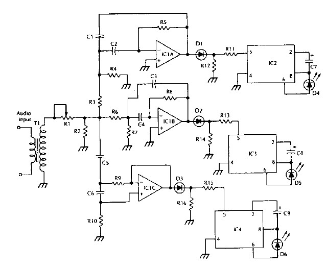
The circuit design leverages the LM3909 LED flasher IC, renowned for its capability to produce flashing LED effects based on audio input. The color organ project begins with three active filters, each tuned to a specific frequency band of the audio signal. These filters separate the audio spectrum into low, mid, and high frequencies, allowing for a more dynamic visual representation of the sound.
Following the filtering stage, rectifiers are employed to convert the filtered audio signals into a suitable form for the LM3909 IC. The rectifiers ensure that only the positive portions of the audio signal are used to trigger the flashing effect. Each of the three ICs (IC2, IC3, and IC4) is connected to one of the rectifiers, allowing them to respond to the respective frequency bands.
The LM3909 IC is configured to flash the connected LEDs (D4, D5, and D6) at a rate of 6 Hz, which is optimal for visual synchronization with the audio input. The choice of different colored LEDs enhances the visual effect of the color organ, making the project not only functional but also visually appealing. The use of distinct colors for D4, D5, and D6 adds an additional layer of complexity to the design, as each LED will illuminate in response to different audio frequencies, creating a colorful display that reacts dynamically to sound.
In summary, this project exemplifies the application of the LM3909 LED flasher IC in creating an interactive and engaging electronic display that synchronizes with audio input, making it suitable for various entertainment and educational purposes.Using LM 3909 LED flasher IC, can be designed various electronic projects. As you can see in this circuit diagram, using the LM3909 LED flasher IC can be designed a very simple color organ. All of three active filters drives the audio spectrum into three bands drive rectifiers and then drive IC2, 3 and 4, flashing the LEDs at 6 Hz.
D4, D5 and D 6 should be three different colors for best effect. 🔗 External reference
Related Circuits
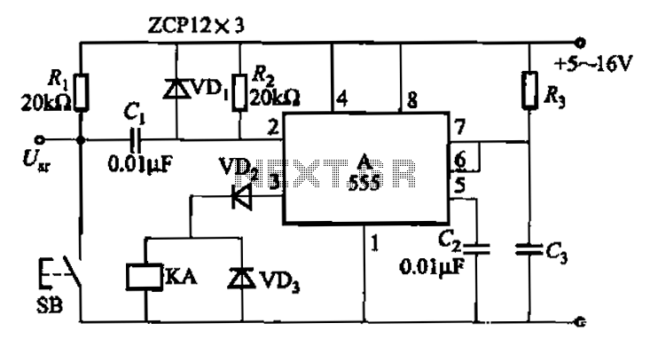
The 555 integrated circuit is utilized in a delay circuit configuration, functioning as a one-shot timer. The delay time can be adjusted using resistor R3 and capacitor C3. Typical values for R3 range from 1 kΩ to 10 MΩ,...
Automatic Gain Control (AGC) is a circuit design that maintains a consistent level of amplification for sound or radio frequency signals. If the signal is too low, the AGC increases the gain to ensure the output remains at a...
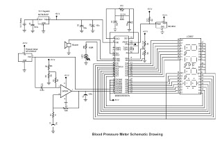
This digital circuit outlines a concept for a digital blood pressure meter that incorporates an integrated pressure sensor, analog signal conditioning circuitry, microcontroller hardware/software, and a liquid crystal display. The sensing system measures cuff pressure (CP) and extracts pulses...
The schematic for an infrared burglar alarm circuit is depicted in Figure 1. The infrared transmitter operates as a multivibrator with an oscillation frequency of 40 kHz, utilizing the NE555 integrated circuit (IC2), along with resistors R1 and R2...
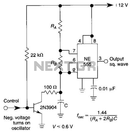
This gated 1-kHz oscillator provides a press-to-turn-on functionality, with waveforms available at the output of pin 3 and across capacitor CI. The gated 1-kHz oscillator circuit is designed to produce a square wave output that can be activated by a...
This simple circuit is started running by connecting a twelve volt battery across the terminals, causing the large diameter Light-Emitting Diode to light up. When the battery is removed, the LED stays lit up because the circuit has become...