
Projects
This project involves the design and construction of a high-power RF transmitter utilizing the GM100 directly heated triode. The GM100 triode is notable for its high voltage and current ratings, making it suitable for amateur radio applications where power output is critical. The design incorporates a variable capacitor and inductor to form a tank circuit, which is essential for tuning and frequency stability. Ferrite beads are employed on the grid and anode leads to suppress parasitic oscillations, a common challenge in high-power RF circuits. The use of a single turn link winding for output extraction is a strategic choice to maintain the integrity of the tank circuit and avoid excessive damping, which can degrade performance.
The power supply for the GM100 triode is a critical component, requiring careful design to handle high voltages safely. The project anticipates using 1 kV to 2 kV HT supplies to achieve optimal performance, necessitating adequate insulation and protective measures to prevent electrical hazards. The current improvised power supply setup will need to be replaced with a more robust design to ensure reliable operation under high voltage conditions.
The goal of achieving 20 watts of RF output at 1.9 MHz demonstrates the potential of the design, with plans to further enhance performance to reach higher outputs while maintaining harmonic suppression. The project also highlights the importance of frequency stability in amateur radio applications, as variations can lead to interference and reduced operational effectiveness.
Overall, this project exemplifies the challenges and considerations involved in high-power RF transmitter design, particularly in the context of amateur radio experimentation. The transition from breadboarding to a more permanent setup will require careful attention to component selection, circuit layout, and safety measures to ensure successful operation.This project was inspired by a sense of wanting to build something a little unusual rather than with the expectation that it would become a useful transmitter. At the time of writing I`m at the breadboarding stage and have yet to decide if I will keep the unit in its current form or dismantle it to re-use some of the parts in other projects.
One of my friends egged me on to build this device and although the rather large size of the valve is more his enthusiasm, I did get to wondering if I could actually use this on air. The valve is a Russian made "GM100" directly heated triode. This valve will withstand anode voltages of up to 5 kV, pass currents of up to 1. 6 amps (!) and has an anode dissipation of 1 kW. The filament takes a massive 18 amps at 17 volts although the only slightly suitable transformer I have drives the heater to about 15. 5 volts which is still pretty bright. To give some idea of the scale, the tiny tube on the left (by the multimeters) is a 12AT7 double triode, the larger tube on the right hand is a 3-500Z, a modern 500 watt triode.
The variable capacitor and inductor shown in the photograph are moderately big components, at least by UK ham standards, but are dwarfed by the huge tube. Having "short" wiring is obviously quite difficult on something so large but ferrite beads on the grid and anode leads seem to have prevented parasitic oscillations.
To run this tube at full power much larger components would be required and the wooden frame would probably be a fire risk! The whole rationale behind this transmitter is to under-run the tube in the interests of frequency stability and longevity although the heater power consumption is a little excessive.
The circuit I`ve used for this is identical to that of the 812 Hartley shown further down the page. At the time of writing, 20 watts of RF has been obtained at 1. 9 MHz with a 730 volt supply drawing about 55 mA and a good 80 watts output with 1300 V and a little over 100 mA. The harmonics are -30 dB WRT to carrier (or better), not a great figure but ok with a low pass filter or at a low power.
Like the 812 Hartley, the output seems best taken via just a single turn link winding so as not to overdamp the tank circuit. I`ve a fair amount of work to do to make this into a viable radio. Firstly I have to ensure the frequency stability and tone are good enough to use on air and secondly I have to complete the PSU circuit; at present it`s a bit of a lash up.
The unit will probably operate best using 1 or even 2 kV HT and so some form of enclosure or restricted access is (obviously) essential. Most of the experimenting has been done with only 100 or 200 volt HT. My progress on the 40m SSB transceiver project has been stalled since June and so I thought I`d put it on the back burner and build another (relatively) small project to get over the blues!
A little travel this year has highlighted the fact that I have no portable Ham equipment and so I decided to build a small valve receiver for the 40m band. A rather obvious advantage of the higher frequency bands is that they require smaller aerials and so are more suited to portable/temporary operation than say 80m or 160m.
I decided that I might have trouble getting a regenerative receiver to perform as well as I wanted on 40m and so elected to use the sl 🔗 External reference
Related Circuits
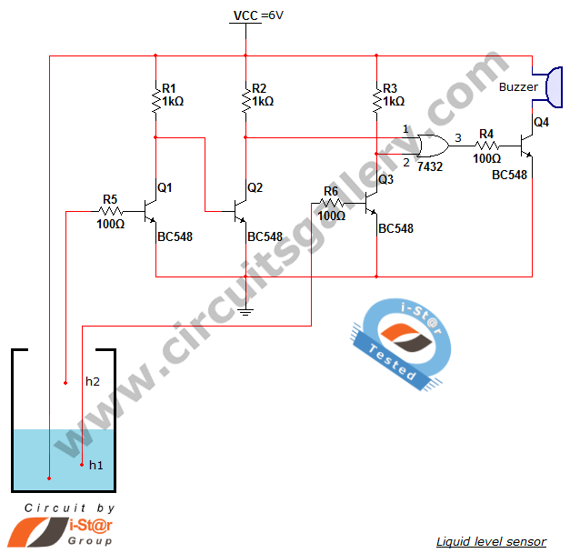
A variety of small electronic projects related to water level sensors have been posted in the Circuits Gallery. This particular project is designed for school students to detect the water level within a water tank or any other water...
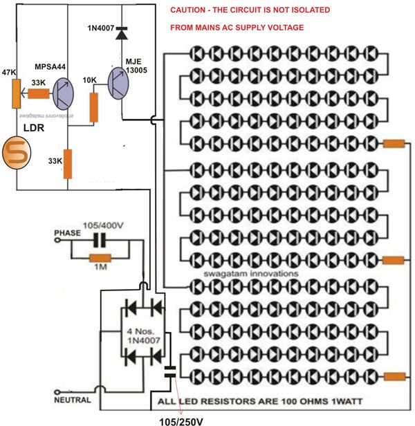
At times, it is quite frustrating to see street lights remaining switched on even during broad daylight. The current circuit for an automatic night light can effectively address this issue. This article explains how to construct such a system....
The development of this interface for Echolink took some time. It utilizes the PIC16F84A microcontroller and accepts external DTMF signals from a radio. The latest version, Foxecho-k7, provides complete isolation between the radio and the PC and features automatic...

This project involves the DiSEqC-Tester, which is designed to test DiSEqC switches utilizing protocols 1.0 and 1.1. The device is compatible with DiSEqC switches that follow protocols 2.0 and 2.1, as they maintain backward compatibility with the earlier versions....

Nowadays, every institution requires automation. As part of college automation, a project has been developed titled "Voice Interactive System for College Automation." This project enables users to quickly access student attendance and marks through a telephone line without the...
Microcontrollers and Microprocessors - The 8051 Projects Page! Discover comprehensive information on 8051 projects here. Everything you wanted to know about 8051 projects is available. The 8051 microcontroller, developed by Intel in the 1980s, is a widely used microcontroller in...
Warning: include(partials/cookie-banner.php): Failed to open stream: Permission denied in /var/www/html/nextgr/view-circuit.php on line 713
Warning: include(): Failed opening 'partials/cookie-banner.php' for inclusion (include_path='.:/usr/share/php') in /var/www/html/nextgr/view-circuit.php on line 713