
Water level sensor circuit: projects for school students
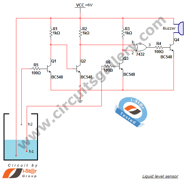
The water level sensor circuit utilizes a straightforward design that highlights the functionality of NPN transistors and logic gates. The BC548 transistors are pivotal in controlling the circuit's states based on the water levels. The circuit operates on a dual threshold mechanism, employing two distinct water level points: h1 for low-level detection and h2 for overflow detection. The integration of the 7432 OR gate allows for simultaneous monitoring of both conditions, ensuring that the buzzer is activated regardless of whether the water level is too low or too high.
In operational terms, when the water level is at or above h2, transistor Q1 is activated, which keeps Q2 in the OFF state, thereby allowing the circuit to remain inactive. Conversely, if the water level drops below h1, Q3 turns OFF, resulting in a high output from the OR gate and subsequently activating Q4, leading to the buzzer sounding an alarm. This dual functionality makes the circuit an effective solution for managing water levels in tanks, promoting efficient water usage and preventing overflow situations.
The circuit can be powered by a 6V power supply, making it suitable for various applications. The choice of components, particularly the BC548 transistors and the OR gate IC, ensures reliability and ease of implementation for students. Overall, this project not only serves as an educational tool but also provides practical insights into electronic circuit design and water management systems.I have posted wide varieties ofsmall electronic projects onwater level sensor in Circuits Gallery. This is another project for school students to detect the water level inside a water tank or any other water reservoir. We can call this as a liquid level sensor`, because this circuit is able to sense the presence and absence of liquid in a tank.
Th is school electronic project is built around BC548 transistors and a 7432 OR gate IC. This water alarm will produce a beep sound when the water goes below a specified level (h1) or when the water overflows. This is one of the home science experiments that can be implemented as science projects for high school students.
You may also like to have a look at our other science experiments like automatic water tank level controller and numeric water level indicator. I have also published an article to detect overflow of water using alarm. The basic principle of this circuit is switching property of NPN transistors `. That is when a transistor is OFF` its collector voltage is Vcc (6V) and when it is in ON` state the collector voltage falls to 0.
02V (approx. 0V). When water level goes below h1` the wire from transistor Q3 disconnects from the power supply, hence Q3 becomes OFF`. Thus its collector voltage will be Vcc. This high` voltage is applied to the OR gate (IC7432)`. Hence its output becomes high (if any one of the input of OR` gate is high, output will be High`) and it leads to the turning ON` of the driver transistor Q4.
Thus the buzzer produces a beep sound. When the water level goes above h2` Q1 becomes ON because its base terminal is energized by Vcc in the water, due to this Q2 will be in OFF` state. So the collector voltage of Q2 becomes High`. Again this High` voltage is given to the OR gate making its output High` and it causes turning ON` of the driver transistor Q4.
Buzzer will start producing sound. 🔗 External reference
Related Circuits
The circuit functions as a sensor capable of triggering an alarm without direct contact from an intruder. It utilizes a visible or invisible light source that illuminates the sensor, maintaining the detection loop in a normally closed state. As...
The schematic diagram described here is a TMP01 Celsius Scale Temperature Sensor circuit. This circuit is used to convert the VPTAT output voltage. The TMP01 is a temperature sensor integrated circuit designed to provide an accurate temperature measurement in Celsius....
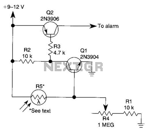
This circuit is a two-wire light level detector, which does not separate the wires for power supply and output signal delivery. It operates using a current loop that performs both functions over a single pair of cables, requiring only...

This simple circuit can be used to sense the distance between the rear bumper of a car and any obstacle behind it. The distance is indicated by the combination of LEDs (D5 to D7) that illuminate: at 25 cm,...
This circuit utilizes a relay to control a water pump, enabling automatic level control for a water reservoir or well. The shorter steel rod acts as the "water high" sensor, while the longer rod serves as the "water low"...
Sensors are utilized in various everyday objects, including touch-sensitive elevator buttons (tactile sensors) and lamps that adjust brightness through touch. The applications of sensors are vast, many of which are unknown to the general public. These applications span across...
Warning: include(partials/cookie-banner.php): Failed to open stream: Permission denied in /var/www/html/nextgr/view-circuit.php on line 713
Warning: include(): Failed opening 'partials/cookie-banner.php' for inclusion (include_path='.:/usr/share/php') in /var/www/html/nextgr/view-circuit.php on line 713