
Propeller Clock
The clock design incorporates a PIC16F84A microcontroller, which serves as the central processing unit for controlling the clock's display and functionality. The modifications made to the original Bob Blick design focus on improving the power supply and reference point for the clock. The power for the spinning assembly is now supplied through a sliding contact mechanism that connects a washer to a 5V source, while the motor's metal casing is grounded. This configuration allows for a stable power supply independent of the clock’s operation.
The reference point for the clock's display is generated using an infrared sensor, which detects a notch on the washer. This approach eliminates the issues associated with the flexible wire previously used, which caused wobbling and noise. The infrared LED, positioned strategically on the motor, enhances the reliability of the pulse detection, ensuring accurate clock operation.
Additionally, the project involves utilizing higher intensity LEDs for improved visibility and aesthetics. The clock's design also addresses previous challenges, such as wear on the sliding contact due to friction over time. A ball bearing from a VCR head is employed to stabilize the motor, along with components sourced from cassette tape players, ensuring a robust assembly.
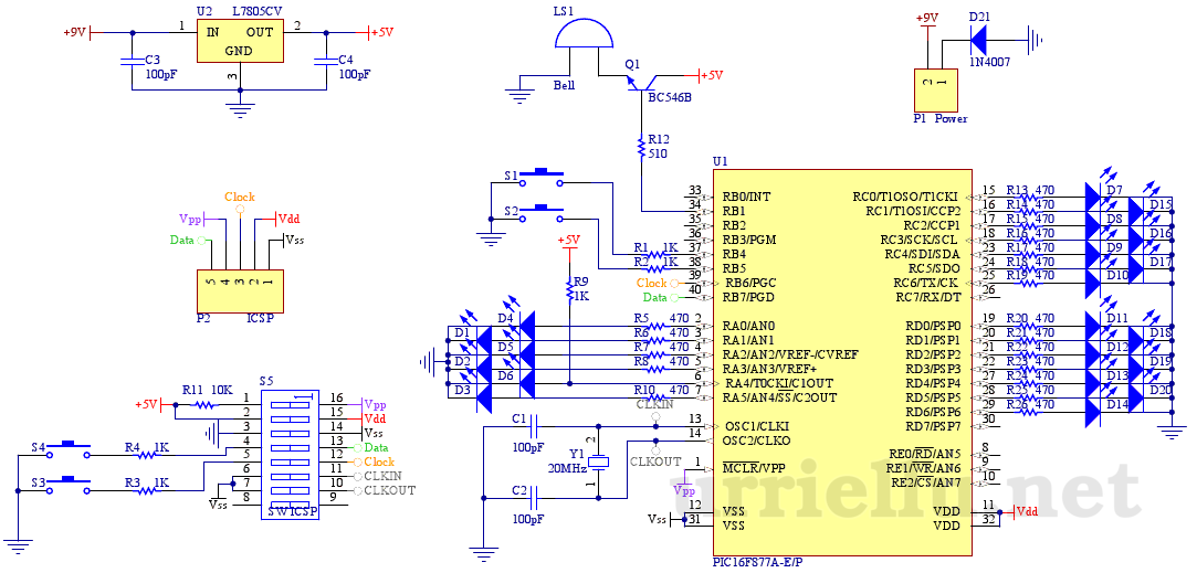
Overall, this project not only pays homage to Bob Blick's original design but also incorporates practical enhancements that improve performance, reliability, and user experience. The programming for the PIC can be sourced from Bob Blick's website, specifically the file named MCLOCK8.HEX, located in the Technical Information and Projects section of the Propeller Clock page. This comprehensive approach ensures that the clock operates efficiently while showcasing the ingenuity of the modifications made throughout the design process.This is one of the most neat projects to build using a PIC. The design of the clock is mainly a clone of Bob Blick `s propeller clock, along with a few modifications of mine. I used a PIC16F84A microcontroller. I`d have to admit that the programming end of things was more difficult than building the clock itself in the beginning.
I originally buil t over five homemade programmers with various software available over the internet, all of which failed to program the PIC. I finally gave up and bought a kit programmer that was not very good either but after fiddling with the software, I managed to program a PIC successfully.
One major modification of Bob Blick`s design is providing power to the spinning assembly. The original design took the power off the spinning armature of a DC motor and converted it to striaght DC for the clock. I have tried this modification on two motors and the results were not very satisfactory; either it resulted the motor rattling a little or it did not work efficiently.
I also learned that the original design had a. 047F (FARAD) capacitor for memory and I did not have a such capacitor on hand, so I decided to make some modifications. Instead, I put a rubber plate above an unmodified DC motor for insulation and a washer on top. The metal case of the motor is connected to ground, and the washer was connected to 5V. The spinning board obtains the 5V through a sliding contact to the washer, and ground through the spinning center of the motor that is also part of the grounded body.
This modification worked very well, but there was the problem of providing a display reference point for the clock. The original design obtains the reference point from one of the terminals on the armature. I put a small notch on the outer end of the washer and put a pick-up wire on the spinning board to pick up the pulse from the notch.
This worked but I was not satisfied by the display occassionally wobbling because the flexible wire does not always keep its position after it hits the notch and also this caused a soft clicking sound that was irritating. Therefore, I replaced the wire with an infrared sensor and installed an infrared LED on the side of the motor.
One advantage from this overall modification is the fact you can provide variable speeds on the motor, since the power to the motor is completely independent of the power to the clock. You could turn off the motor and still set the clock, which omitted the need of a. 047F memory capacitor. Below is a schematic of my clock: The program for the PIC can be found at Bob Blick`s website, the filename is MCLOCK8.
HEX and is located on the Propeller Clock page in the Technical Information and Projects section. I decided to rebuild the original propeller clock using higher intensity LEDs. However, the original propeller clock had some problems with the sliding contact being eaten away due to friction over time. Also the board was built a year before the clock was actually up and running (I admit I couldn`t figure out how to program the PIC in a long time!), so there were several modifications on the wiring, which resulted in some brittle connections and intermittent operation.
Bottom line, I needed to build a new one. I reused some parts from the original clock, especially the PIC and also used a revised code somewhere on the internet to add the seconds to the display. I found a nice motor in my junk pile that probably was used in an old laserdisc player if I remember correctly.
I decided to build this clock using the classic Bob Blick style, obtaining power from the armature of the motor. I was fortunate to pull this off with this motor, since all other previous motors failed to run smoothly when I was building the original clock.
I used a ball bearing from a VCR head to hold the top end of the motor in place, plus some other parts from cassette tape players. Since this clock does not obtain power independently from 🔗 External reference
Related Circuits
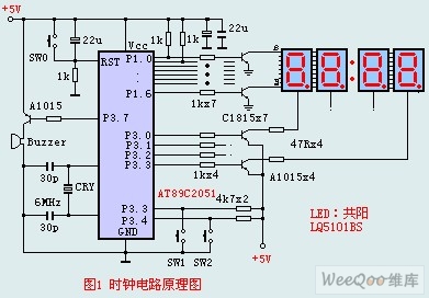
The circuit design incorporates an anodic Nixie tube for the LED display. It utilizes the LQ5101BS general luminous diode, with the driving transistor being either the 2SA1015 or 2SC1815 types, which are readily available. Additionally, low-power transistors such as...
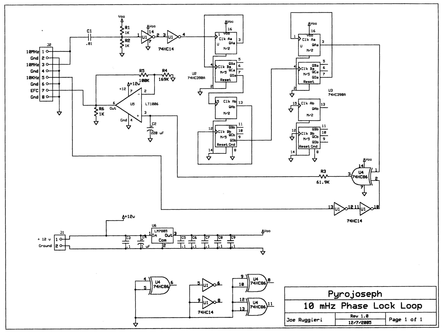
The block diagram illustrates that a 10 MHz signal is generated by an oven-stabilized 10 MHz crystal oscillator, which is locked to a precision 10 kHz signal produced by a GPS receiver module through a phase-locked-loop (PLL) circuit. In...
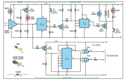
This design allows for the construction of an electromagnetically impulsed pendulum clock with a 1-second beat. The prototype features a pendulum rod measuring 115 cm in length, with a bob adjusted to achieve a 1-second beat. It is suspended...
This is the second part of the square root algorithm. It was developed during the final stages of finishing this website and reviewing this document for publication. While Part I focused on an empirical discovery for a sequential algorithm...
This is the first electronic circuit designed from scratch, marking the initial experience with programming a microcontroller (MCU), the first application written in assembly language, and the second homemade printed circuit board (PCB). While it is common for individuals...
Parallax, known for its successful Basic Stamp integrated circuit (IC), has recently launched the Propeller: a new microcontroller that features a unique design. It incorporates eight 32-bit processors, referred to as COGs in Propeller terminology, within a single 40-pin...
Warning: include(partials/cookie-banner.php): Failed to open stream: Permission denied in /var/www/html/nextgr/view-circuit.php on line 713
Warning: include(): Failed opening 'partials/cookie-banner.php' for inclusion (include_path='.:/usr/share/php') in /var/www/html/nextgr/view-circuit.php on line 713