
GPS-Disciplined 10 MHz Frequency Standard / GPS-Based Universal Time Clock
The electronic schematic described involves several critical components working in concert to produce stable frequency outputs. The primary component is the oven-controlled crystal oscillator (OCXO), which serves as the main frequency source, generating a stable 10 MHz signal. The PLL circuit locks this oscillator to the 10 kHz signal derived from the GPS module, enhancing frequency accuracy and stability. The GPS module, which can be any compatible unit that provides a 10 kHz output, plays a pivotal role in maintaining synchronization with global time standards.
The RS-232 level converter is essential for interfacing the GPS output with the PIC microcontroller, ensuring that the data format is compatible for processing. The PIC microcontroller decodes the NMEA data, which contains vital information such as geographic coordinates and universal time. This data can be displayed on a user interface or sent to other devices for further applications, including satellite tracking.
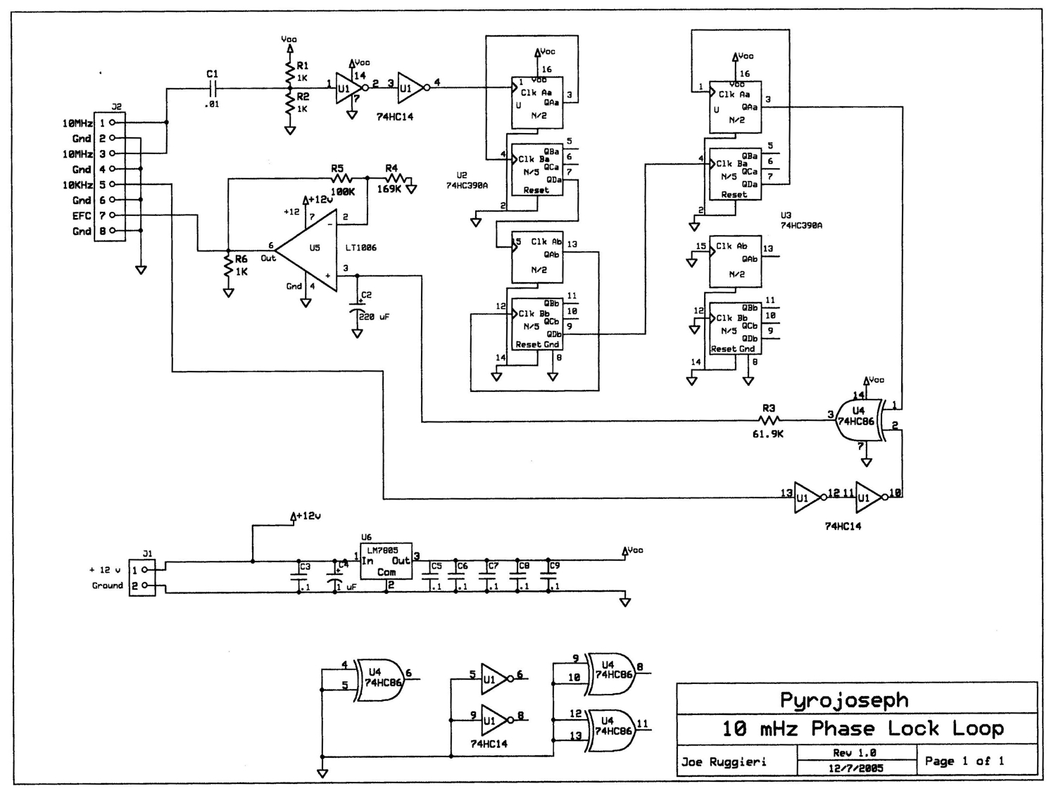
Powering the PLL circuit with a 12 VDC supply is necessary for its operation, ensuring that the PLL can maintain the frequency lock effectively. The design and construction of the PLL circuit by Joe Ruggieri provide a reliable solution for achieving the desired frequency stability and precision.
Overall, this system exemplifies the integration of various electronic components to achieve high-performance timekeeping and navigation capabilities, leveraging both crystal oscillator technology and GPS-derived signals for enhanced accuracy in timing applications.As shown in the block diagram above, the 10 MHz signal is produced by an oven-stabilized 10 MHz crystal oscillator that is locked by a phase-locked-loop circuit (PLL) against the precision 10 kHz signal generated by the GPS receiver module. In addition to the 10 MHz signal, precision 10 kHz and 1 Hz signals are also output by the system. The 1 Hz signal is especially useful as a precise 1 pulse-per-second reference for clocks that can accept such input. The raw NMEAdata generated by the GPS receiver is sent to a RS-232 level converter and to a PIC microcontroller. The PIC decodes the data and displays exact location and universal time information. The RS232data are sent to instruments around my shack that can use it, for example for precision satellite tracking with my space-communications antenna array.
The GPS receiver that I used is a surplusOEM unit made by Rockwell (information available here: Rockwell_Jupiter_GPS ). However, any other GPS module that outputs a GPS-derived 10 kHz signal may be used. The PLLcircuit (click on the figure to enlarge)was designed by Joe Ruggieri(AKA eBay Pyrojoseph) and constructed on a circuit board that he sells.
The circuit connects directly to the 10 MHz OCXO and to the 10 kHz output from the GPS module. The circuit requires 12 VDC, which I feed from an external power supply. As shown in the following figure, the GPS-disciplined oscillator performs superbly as evidenced by comparing its output to that of my rubidium atomic clock reference : 🔗 External reference
Related Circuits
The reception of 2-meter signals typically utilizes a converter and a shortwave receiver, preferably of the communications type, which should exhibit above-average sensitivity and selectivity. This equipment arrangement allows for the conversion of the 144 MHz or other VHF...
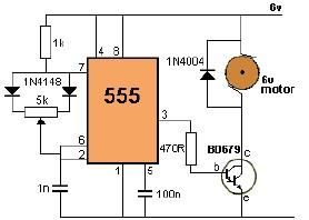
This project utilizes a 555 timer to control the speed of a 6-volt DC motor. Speed adjustment is achieved by rotating a 50 kΩ potentiometer either to the left or right. The circuit employs a 555 timer configured in astable...

A simple circuit that can generate an inverted square wave similar to the one used by the inventor on his function generator. To construct a circuit that produces an inverted square wave, a basic approach involves using a 555 timer...
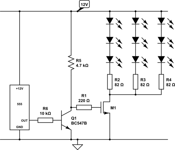
Create a circuit using a 555 timer to operate 72 LEDs simultaneously. A circuit has already been constructed, but there are concerns regarding its safety and longevity. A picture of the circuit is provided for review, and assistance is...
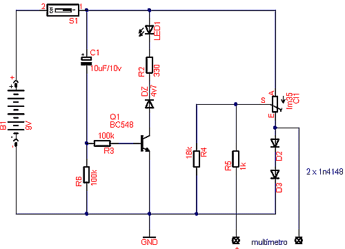
Temperature sensor converter designed for use with a digital multimeter, capable of measuring temperatures from -40 °C to 110 °C. It features a state indicator and requires no calibration, utilizing the LM35 integrated circuit. The freezing point of water...
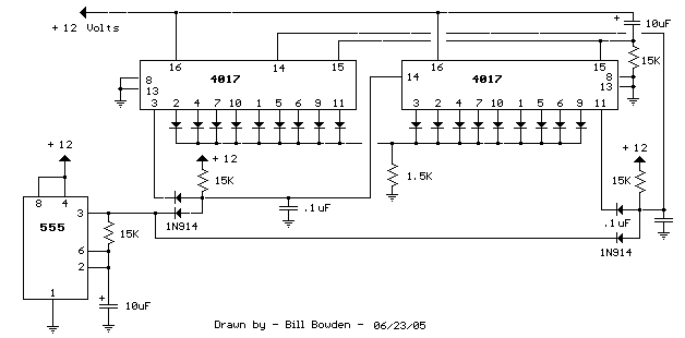
The question sometimes comes up of how to cascade 4017 decade counters for more than 10 sequential stages. The LED sequencer below shows a possible solution using a few extra parts. When power is applied, the 15K resistor and...