
Proximity Mask Head (A2045) Manual
This higher current will, no doubt, reduce the operating lifetime of the LEDs. Not only did the ATLAS circuits pass too much current through the LEDs, they also allowed too much power to be dissipated in transistor Q1. Resistors R3 and R4 were only 47 ©, instead of the 75 © we show in the schematic. Transistor Q1 has 8 V across it instead of 1. 7 V. It must dissipate 800 mW instead of 200 mW. The transistor is designed to dissipate only 500 mW. Twenty-four hours of continuous operation (as described here ) is enough to damage this transistor in either the ATLAS A2045s or the ATLAS A2052s.
Most damaged circuits can still flash its LEDs brightly, but not for longer than a few seconds. If we turn on the LEDs, their power output remains steady for several seconds, flickers, and drops to roughly 1% of its previous value. If we hold the board vertically, and blow on it to keep it cool, the LEDs might keep shining at 100% power for a minute, but eventually flicker and turn off.
If remove power from the circuit and wait for a full five minutes, we find that the circuit has recovered, and will drive the LEDs at 100% power for a few seconds once again. If we replace Q1 in any of these damaged circuits, the board is as good as new. We do not claim to understand this transistor failure, but we that is what we observed in all five broken A2045s returned from CERN, and all three broken A2052s from our demonstration stand.
The LWDAQ specification requires that no LWDAQ device can be damaged by any sequence of command transmissions. The A2045 in an enclosure can be damaged simply by turning it on and leaving it on. This does not happen in normal operation, but does occur after power supply surges that cause its command register (U11) to re-start in an undefined state.
Random power surges at CERN appear to have left Proximity Mask Heads (A2045L and R) turned on until Q1 fails. When we received such boards back from CERN, we replaced Q1 and they worked again. We will explain, for those who are curious, how our circuit design went wrong. (Please refer to the schematic for part names. ) Resistor R5 controls the current through the LEDs. In the ATLAS circuits, it was 15 ©. The three diodes of U7, a MA125, pass of order 1 mA, and we supposed they would drop 0. 6 V each, or 1. 8 V total. The base-emitter drop of PNP transistor Q1, a FMMT591A, will be roughly 0. 8 V at the LED operating current. This leaves 1. 0 V across R5. The ATLAS circuits had R5 of 15 ©, so we anticipated 75 mA through the LEDs. But it turns out that the diodes of U7 have a total drop of closer to 2. 1 V, and Q1 at 100 °C has a base-emitter drop of only 0. 4 V at 100 mA. We are left with 1. 7 V across R5 instead of our anticipated 1. 0 V, and the LED current is 110 mA. With 110 mA flowing through the LEDs, and 47 © for R3 and R4, these two resistors together drop only 10.
3 V of the 30 Volts available from the ±15-V supplies. The HSDL-4400 LEDs themselves have a typical forward voltage drop of 1. 5 V at 50 mA, and this is what we observed in our prototype circuits. But the LEDs we used in our A2045 and A2052 boards have forward voltage drop of only 1. 3 V at 110 mA. We are left with 30 ’ 10. 3 ’ 1. 7 = 6. 3 V across Q1, and 110 mA, or a total power dissipation in its SOT-23 package of 700 mW, well above its maximum continuous dissipation in free air of 500 mW. The lower than expected drop across the LEDs, combined with our errors in designing the current source, cause excessive power dissipation in Q1.
It is too late for us to modify our ATLAS A2045s, but if you want to make some more, we recommend that you use the resistor values shown in the schematic, where we R5 is 22 ©, and R3 and R4 are 75 ©. If you have a circuit with R5 of 15 © and R3 and R4 of 47 ©, the quickest way to fix it is by changing R3 to 100 ©.
This change will reduce the voltage across Q1 from 6. 7 V to 1. 7 V, and so avoid overheating. We applied this change to hundreds of existing Inplane Mask Heads ( A2052 ). The modified boards suffered no damage from over-heating even after continuous operation for 200 hours, as described here. We provided approximately 1400 A2045s for the ATLAS experiment, as well as 1100 A2052 s. The A1052 circuit is identical to that of the A2045. The following table lists the errors we found on boards returned by our colleagues at CERN and marked as malfunctioning in some way.
🔗 External reference
Related Circuits
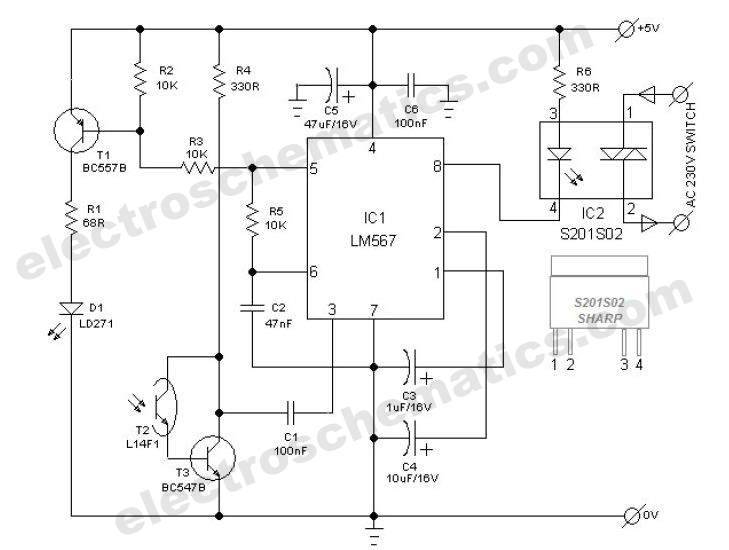
The power switch with an infrared proximity sensor is designed to detect obstructions at distances ranging from a few millimeters to several centimeters. The power switch utilizing an infrared proximity sensor operates on the principle of emitting infrared light and...
The ICX424 Minimal Head (A2075) features a single ICX424 image sensor and an optional pair of illumination LEDs. Power and drive signals enter the circuit board through a twelve-way flex connector. Three capacitors provide local decoupling of the supplies....
The objective of Linkwitz's article was to reduce distorted spatial reproduction when listening to recorded stereo music with headphones, addressing the "super stereo" effect where the music appears to originate from within one's head. To eliminate this spatial distortion,...
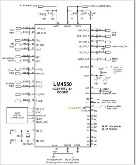
The LM4610 is a DC-controlled tone (bass/treble), volume, and balance circuit designed for stereo applications in car radios, televisions, and audio systems. It also incorporates National's 3D-Sound circuitry, which can be adjusted externally using a simple RC network. An...
To design a Tube Headphone Amplifier we need a triode with uncommon characteristics: enough voltage gain, low internal resistance and good anodic current. My first test was done with the E182CC, but there is the limitation on the usable...
Both halves of the circuit are identical. Both inputs have a DC path to ground via the input 47k control, which should be a dual logarithmic type potentiometer. The balance control is a single 47k linear potentiometer, which, when...
Warning: include(partials/cookie-banner.php): Failed to open stream: Permission denied in /var/www/html/nextgr/view-circuit.php on line 713
Warning: include(): Failed opening 'partials/cookie-banner.php' for inclusion (include_path='.:/usr/share/php') in /var/www/html/nextgr/view-circuit.php on line 713