
ICX424 Minimal Head (A2076) Manual
The A2076 circuit is engineered to facilitate the integration of the ICX424 image sensor into various optical systems, emphasizing versatility in both monochrome and color applications. The design incorporates a robust power management system, ensuring that the sensor operates efficiently under different conditions. The inclusion of decoupling capacitors serves to stabilize the power supply, minimizing fluctuations that could affect sensor performance. The direct routing of the image sensor output to the connector is a critical design choice, allowing for rapid signal transmission while mitigating the need for additional buffering, which could introduce latency or noise.
The lens holder's specifications, including a 12-mm diameter and a 0.5-mm pitch thread, provide compatibility with a wide range of lens assemblies, enhancing the system's adaptability for various imaging requirements. The ability to focus the camera through mechanical adjustments ensures optimal image quality across different operational scenarios.
The illumination system, particularly in the A2076C variant, is designed to enhance visibility in low-light conditions, with the option to control LED operation either continuously or via an external control signal. This flexibility is crucial for applications requiring precise imaging in varying light environments.
The connection methodology via a 12-way flex cable highlights the design's emphasis on ease of integration with existing systems while maintaining the integrity of signal transmission. The non-polarized nature of the connectors further simplifies installation, reducing the risk of user error during setup.
Overall, the A2076 series represents a sophisticated approach to image sensor integration, combining flexibility, efficiency, and compatibility with a range of optical components, making it suitable for advanced applications in scientific research and industrial imaging.The ICX424 Minimal Head (A2075) holds a single ICX424 image sensor and an optional pair of illumination LEDs. Power and drive signals enter the circuit board through a twelve-way flex connector. Three capacitors provide local de-coupling of the supplies. The image sensor output is routed directly to the connector without buffering. The A2076 opera tes in conjunction with IXC424 drive board such as the Camera Head ( A2075 ). The A2076 will accommodate both the monochrome (IXC424AL) and color mosaic (IXC424AQ) versions of the image sensor. For a detailed discussion of these sensors see the A2075 Manual. Figure: A2076A with Image Sensor. Silk screen markings and mounting holes locate a CMT821 lens holder, which provides an 12-mm diameter, 0.
5-mm pitch thread for lens assemblies. The thread allows us to focus the camera. This version provides no LED illumination. The A2076A and A2076B use the same circuit board, the A207601A, but are equipped with the ICX424AL monochrome and ICX424AQ color mosaic image sensors respectively. The board provides mounting holes on each corner, as well as two mounting holes for a lens holder. The lens holder accepts any lens assembly with an M12, 0. 5-mm pitch thread. Figure: A2076A with Fish-Eye Lens. The lens is a DSL215 mounted in a CMT821 lens-holder. The circuit is oriented so that it provides a an upright image in the Camera Instrument, and held in place with yellow mounting clay.
The A2076C, shown below, provides two LEDs in 3-mm radial packages for illumination of the field of view. As shown in the circuit diagram, the LEDs are connected in series to +15V. We can either provide a permanent path to 0V through resistor R1, or we can connect power to the LEDs using the L signal on J1-11.
In the circuit shown below, we use R1 to provide power whenever +15V is connected to the circuit. Figure: A2076C Mounted on Aluminum Tube. The lens is a DSL821 mounted in polysulfone plastic. The two red LEDs are symmetric about the lens, just visible through the plastic. Instead of one P2010 power dissipation resistor for the LEDs, we use two P1206 resistors in parallel. Although we designed the A2076 to work with the ICX424AL and ICX424AQ image sensors, the larger ICX204AL and ICX204AK image sensors are also, in theory, compatible with the A2076.
These sensors are monochrome and color mosaic respectively, provide the same image area, but with an array of 1034 G— 779 pixels. The A2076 can provide two LEDs (light-emitting diodes) for illumination. Depending upon the version, these LEDs will turn on whenever power is supplied to the image sensor, or they will turn on only by means of the A2076`s L control input.
With LED1 and LED2 installed and a 0. 5-W 47- © resistor in place of R1, the lamps will shine whenever the image sensor has power. With LED1 and LED2 installed, but R1 omitted, the lamps will turn on only when the L control input draws current out of them. Connect the A2076 to a ICX424 read-out device such as the Camera Head ( A2075 ). Make the connection with a 12-way, 1-mm pitch flex cable. The connector on the A2076 can be one with contacts only on one side of the flex cable or upon both sides.
Flex cables and connectors are not polarised, so it is easy to plug the cable in the wrong way. If the connector has contacts on both sides, the power and drive signals will be delivered to the A2076 in reverse order. But the pinout of the connector is chosen to make it tolerant of a reversal of the cable. Thus we can plug the cable in one way, see if the sensor works, then switch it around, without fear of damaging the circuit.
In order to interpret the geometry of the acquired image in terms of the image sensor surface, you will need to locate pin one of the image sensor package, and consult the geometry section here. Finding pin one on the image sensor package is best done by looking for the pin with the thicker base, as shown below.
Because the cable carries the output signal back to the drive board without buffering, we expect to see image noise increasing with the length of the flex cable. Cross-talk between the clock signals and the pixel intensity will be synchronous, so we do not expect this source of noise to be significant.
But pick-up of external interference will increase with cable length. The vertical clock signals have at least 7 s to settle after each transition, because they are controlled by LWDAQ command transmissions to the drive board. Thus we doubt that flex cables of up to 50 cm will have any effect upon their transmission to the image sensor.
The horizontal clock signals are far faster and more likely to distort. We allow 500 ns for each correlated double-sample of the output, and hope that the 5-V horizontal clock signals settle within 50 ns of a transition. Nevertheless, the clock signals should propagate down a 50-cm flex cable in only 2. 5 ns, so we do not expect reflections at the cable ends to cause significant problems. The A2076 provides two LEDs in series for illumination. These can be powered continuously through resistor R1, if present, or controlled through the L connection on J1-11.
Because the ICX424 provides instant clearing and readout with its clearing and readout pulses, there is no need for us to synchronise the flashing of these lights with the clearing, exposure, and readout of the image sensor. Thus it is feasable to use the image sensor with continuous illumination. When we use the A2076C with the A2075, for example, the LEDs turn on whenever the A2075 wakes up. The A2076C together with the A2075C are the first ICX424 circuits designed specifically for application in ATLAS at CERN.
Four A2076Cs mounted on a prototype Long Guide Tube. The LGTQC script reads out all four cameras through a multipexer and displays their images in one window. The images can be read out with high resolution or low resolution. They appear the same size regardless, but the low resolution readout is four times faster. 🔗 External reference
Related Circuits
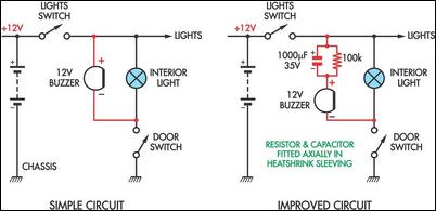
Two headlight reminder circuits are designed for easy installation and operation based on the KISS (Keep It Simple Stupid) principle. The basic circuit consists of a 12V piezo buzzer connected between the lights circuit and a door switch. The...
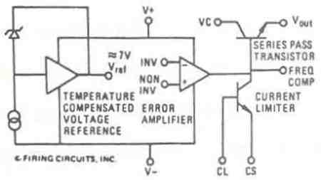
This manual applies to all integral horsepower DC motor controls within this series, ranging from 40 HP to 300 HP. The integrated circuit regulator selection of these DC motor controls is modular in construction, allowing for minimal downtime in...
The LWDAQ Driver (A2037) is a Long-Wire Data Acquisition (LWDAQ) Driver. An introduction to the LWDAQ can be found in the LWDAQ User Manual. The A2037 features eight LWDAQ driver sockets, which can be connected to either a LWDAQ...
The most extreme option would be to supply power through a battery pack. A more plausible source would be the car's battery. However, since the objective of the circuit is to activate the buzzer when the headlights are on,...
Assembly is straightforward; simply follow the PCB overlay. Ensure that the integrated circuit and the electrolytic capacitors are oriented correctly. The electrolytic capacitors are polarized, marked with a + or - sign, and must be installed properly into the...
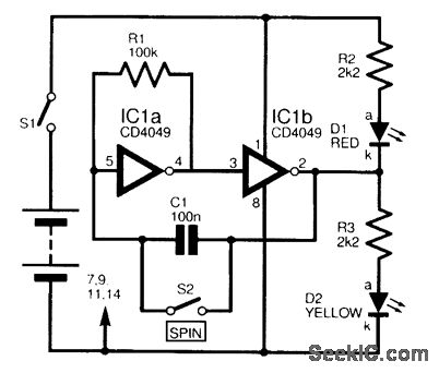
This circuit is designed to electronically simulate the tossing of a coin using a 4049 hex inverter integrated circuit (IC). It employs two of these ICs, specifically IC1a and IC1b, which are configured as an astable oscillator. This configuration...
Warning: include(partials/cookie-banner.php): Failed to open stream: Permission denied in /var/www/html/nextgr/view-circuit.php on line 713
Warning: include(): Failed opening 'partials/cookie-banner.php' for inclusion (include_path='.:/usr/share/php') in /var/www/html/nextgr/view-circuit.php on line 713