
Microcontroller In Circuit Serial Programming (ICSP) with Microchip PIC and Atmel AVR
 with Microchip PIC and Atmel AVR")
In-Circuit Serial Programming (ICSP) is a technique that allows for the direct programming of a Microchip PIC or Atmel AVR while they remain connected to a circuit, as opposed to programming the chip beforehand and subsequently soldering it into the circuit. ICSP offers numerous advantages, but it also presents critical design considerations that warrant attention.
ICSP facilitates the reprogramming of microcontrollers without the need to desolder them from the circuit, thereby simplifying the development process and enhancing efficiency. This method is particularly beneficial during prototyping and testing phases, where frequent updates to firmware may be required. The ability to program devices in-circuit reduces the risk of damage associated with repeated soldering and desoldering.
Design considerations for implementing ICSP include ensuring that the programming pins are accessible and that the circuit design does not interfere with the programming signals. It is essential to maintain a clear path for the PGC and PGD signals to avoid signal degradation or noise interference. Additionally, the MCLR/VPP pin must be appropriately managed to prevent unintended resets or erratic behavior during programming.
Careful attention should be given to the layout of the PCB to ensure that the ICSP connections are clearly defined and isolated from other circuit paths. Utilizing dedicated pins for ICSP not only simplifies the design but also enhances reliability during programming sessions. Furthermore, incorporating pull-up resistors on the MCLR/VPP line can help stabilize the programming process and ensure proper operation.
In summary, ICSP is a powerful tool for programming microcontrollers in-circuit, offering significant advantages in terms of efficiency and flexibility. However, careful design and implementation are crucial to maximize its benefits while minimizing potential issues.The programmer uses serial signaling scheme to program the chip in circuit. The signaling is carried through the programming clock (PGC or ICSPCLK) and the programming data (PGD or ICSPDAT) pins. In addition, the MCLR/VPP pin is used as either a high voltage programming signal or an attention indicator to the device.
Wherever application allows, use dedicated pins for ICSP. It will save you much trouble. Not sharing a pin both for ICSP and I/O for example, minimizes the preparation work which needs to be done to allow ICSP. In Circuit Serial Programming is a method of directly programming a Microchip PIC or Atmel AVR while in they are connected to a circuit, as opposed to programming the chip ahead, and only then soldering it to a circuit. There are many benefits to ICSP, but also some important design considerations which I will try to highlight.
🔗 External reference
Related Circuits

This portable solar lantern circuit utilizes a 6 volt/5 watt solar panel, which is widely available. With this photovoltaic panel, an economical, simple, yet efficient and truly portable solar lantern unit can be constructed. The next essential component required...

Differential amplifier circuit with four connection methods and characteristics for comparison. The circuit exhibits magnification with a single tube when symmetrical. Additionally, CMRR (Common Mode Rejection Ratio) is adapted from single-ended input to a double-ended output. The differential amplifier is...

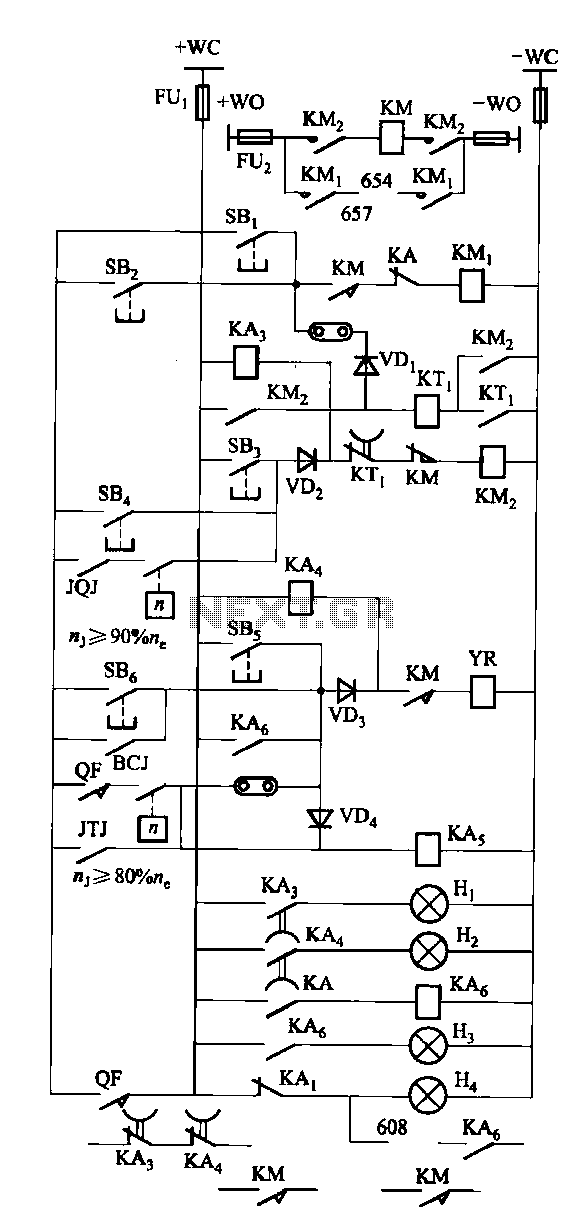
The DW16M-630 type excitation switch operates with both DC and AC power. The circuit for DC operation is illustrated in Figure 7-60, while the circuit for AC operation is shown in Figure 7-61. The BQ single-phase series motor M...

There are digital and analog methods that can be used to compensate for the nonlinearity of a PT100 RTD. Digital linearization can be implemented through various techniques. Compensation for the nonlinearity of a PT100 RTD (Resistance Temperature Detector) is essential...

This page provides information on circuits that can trigger stroboscopes from external circuits. The circuits are designed to be integrated into stroboscope systems, allowing them to be activated using an external trigger pulse. The standard trigger pulse utilized in...
The FKL-32 type automatic thyristor excitation device is designed for synchronous generators with a terminal voltage of 400V and a capacity of 500kW and below. It is used for the automatic adjustment of excitation. The FKL-32 thyristor excitation device is...