
Proximity sensor - Page 2
The described circuit involves a theremin/controller setup that utilizes control voltage (CV) to manage audio effects, specifically a wah effect. The instability noted in the circuit may be attributed to temperature sensitivity, which can affect the performance of both the theremin and the associated audio processing circuit.
In this configuration, the theremin generates a control voltage that varies based on proximity to the antenna, which is a fundamental principle of its operation. The CV output is crucial as it modulates the behavior of the audio wah circuit. By replacing the traditional potentiometer with an LDR, the circuit introduces a light-sensitive element that responds dynamically to changes in the environment, specifically the intensity of the LED light.
The optocoupler formed by the LED and LDR allows for isolation between the control and audio circuits while enabling the modulation of audio signals based on the control voltage. As the hand approaches the theremin's antenna, the increased voltage causes the LED to emit more light, which in turn affects the resistance of the LDR. This variation in resistance alters the signal path in the audio wah circuit, producing a sweeping effect that can be controlled by hand movements.
Overall, this circuit exemplifies an innovative approach to combining analog control with audio processing, leveraging the principles of light and resistance to create a responsive and interactive sound modulation system. Further refinement may be necessary to address the instability issues, particularly in maintaining consistent performance across varying temperature conditions.First of all, the circuit is ok, but it`s rather unstable. It varies with temperature, and, for eg, I turned it on and I tune it. Them I switch it engineer it, if we get to some conclusion I`ll post it here (the conclusion, not the schem :P) Ahh, CV is Control Voltage. The theremin/controller circuit has to have a CV out (control voltage out). Then, the other circuit (audio - in this case, a wah circuit), has a pot. We substitute that pot with a LDR and connect a LED to the CV out of the theremin circuit. Together, the LED+LDR make a optocoupler (vactrol). As I approach my hand to the antenna of the theremin, voltage increases, driving the LED. The LDR reacts to the light emmitted and therefore augments its resistence (or diminishes it) and acts like a potentiometer.
🔗 External reference
Related Circuits
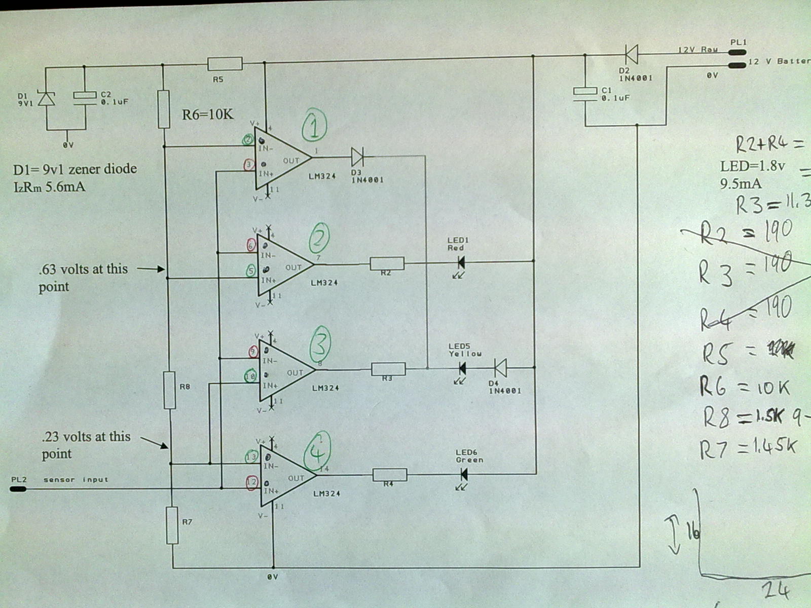
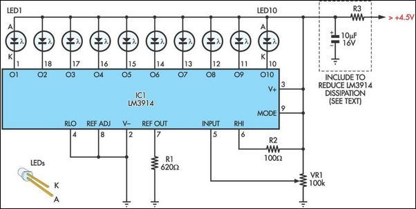
A 12V power supply is connected to the positive terminal, allowing current to flow through a protection diode and a capacitor that smooths the voltage. A zener resistor (R5) limits the current to the zener diode, which regulates the...
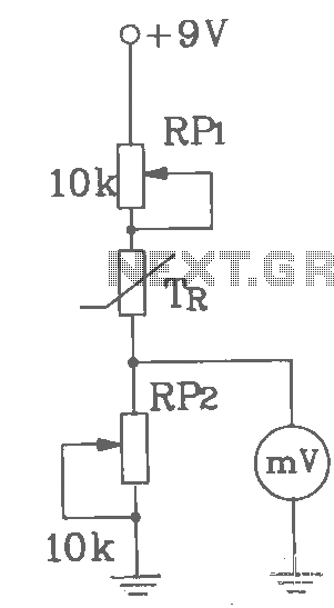
T-121 temperature sensor electronic thermometer circuit diagram shown below The T-121 temperature sensor circuit is designed to measure and display temperature readings accurately. The circuit typically consists of a temperature sensor, such as the T-121, which converts temperature variations into...
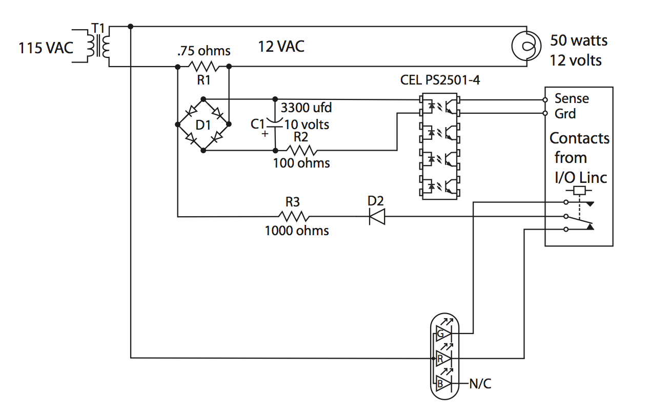
An automatic garage door opener, a seeded back lawn, a fireplace, and a refrigerator were offered. A flagpole was also requested, resulting in the installation of a 25-foot commercial flagpole. The owner has illuminated the flag at night to...

The sensor/monitor depicted in the diagram activates the host system upon detecting infrared (IR) signals. It consumes very little supply current, allowing it to remain continuously operational in devices such as notebook computers or PDAs. The ultra-low current drain,...
Temperature indicators and temperature-based products have garnered significant interest due to their numerous applications and various possible solutions, each presenting unique advantages and disadvantages. This concept focuses on a sensor interface that delivers high accuracy while minimizing board space....
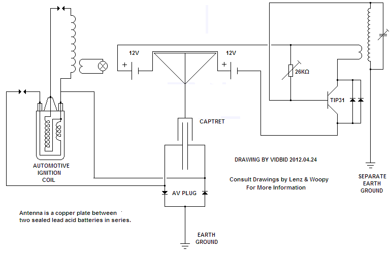
Thank you for the diagram, Zinc. It looks very interesting. Please keep us informed of any results. I am MrFlathunter on YouTube, and you commented on my 12V. The circuit in question likely pertains to a 12V system, which is...