
pulse counting fm receiver
The VHF transistor radio circuit described integrates various components that work together to achieve a functional and efficient radio receiver. The RF amplifier (TR1/2) is critical for boosting weak signals before they reach the mixer. The use of two 2N3819 N-Channel FETs ensures that the radio can handle high-frequency signals effectively while minimizing noise and distortion. The dual gate 40673 MOSFET in the mixer (TR3) is designed to manage the mixing of the RF signal with the local oscillator signal generated by the BF222B transistor (TR4). This configuration is essential for achieving a stable and reliable output signal.
The Intermediate Frequency (IF) section is simplified by using resistance coupling in the BC547 transistors (TR5/6), which reduces the complexity of the circuit while maintaining adequate gain for the low IF frequency of 150 kHz. This choice enhances the robustness of the design, ensuring that it remains operational with minimal adjustments. The pulse counting FM detector, formed by the 2N2369A transistors and 1N4149 diodes, serves as a modern alternative to traditional FM demodulation techniques, providing a straightforward method for extracting audio signals without the need for complex tuning or alignment.
Finally, the audio amplifier stage utilizing the LM386 IC is a well-regarded choice in low-power audio applications, providing sufficient amplification for driving speakers without generating excessive heat, which simplifies the overall design and enhances reliability. The entire circuit is powered by two 9-volt batteries, ensuring portability and ease of use in various environments, such as gardens or during travel. This design exemplifies the integration of modern components with classic radio principles, resulting in a functional and user-friendly VHF transistor radio.This part of my site features construction details of a transistor VHF radio I managed to build using circuits as the building blocks, Compiled from some of my old radio magazines and books. Although this site is titled as a valve radio site I have decided to include transistor radio projects as well and having successfully built a valve version o
f this type of FM Receiver, I have since been itching to have a go at a transistor version for use in the garden and when I go on holiday. The valve version I constructed which is featured on some of the home page pictures referring to my valve portable Hi Fi System is not strictly my own design, But can be found by clicking on the following link Cool386`s Australian Site of Antiquated Technology an excellent website run by John Hunter who also has some great FM Radio circuits and also an update on his valve version of the pulse counting receiver by clicking on this link.
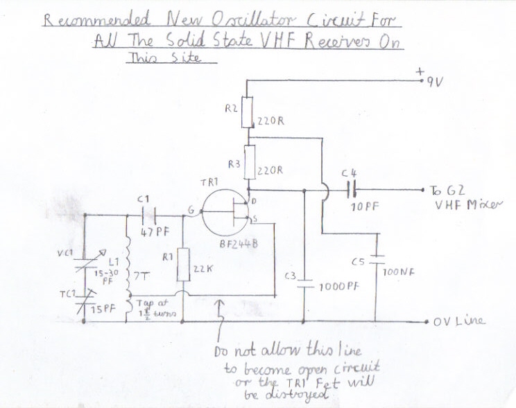
Part of the idea of this design also came from a similar transistor version featured in the August 1967 issue of Practical Wireless. The PW version was slightly behind time. It was featured as a switched version with the Channel positions marked as Light Third and Home, Only just 2 months before the BBC Launched there new network of stations, Starting with Radio 1 available on Medium wave only and Radio`s 2 3 and 4 to replace the exciting three networks.
The PW version although very good at the time had several disadvantages. It used the old Germanium OC171 transistors that had a reputation for being unreliable, Compared to the later Field Effect Transistors such as the 2N3819 series that were apparently just available at that time and could have easily been substituted for the RF / Mixer circuits, Despite a few circuit modifications. The idea of switched tuning is very convenient but that also has a couple of disadvantages regarding RF performance.
In the days of Light Third and Home this was not a problem as there were no Local Radio Stations around at that time, So there was not the need to have to keep tuning like you sometimes do to get a clear station without interference from other channels. Also the idea of bandswitching is not my scene when it comes to VHF work because as you are dealing with a high frequency of 100 MHZ, Leadless connections to the coils and tuningcapacitors are strictly the order of the day, As the risk of poor performance andinstability is very high compared to the Short Wave Bands.
As you can see in the block diagram above this is a description of my design. Starting from right of the picture is the RF amplifier TR1/2 and like valve circuits it works in cascade mode consisting of 2, 2N3819 N-Channel FETs. Although it works quit well without it, Its purpose is to improve image response and help prevent radiation of the local oscillator.
The mixer TR3 is a dual gate 40673 MOSFET and along with TR4 BF222B For the local oscillator this makes a very stable VHF receiver front end with no oscillator pulling, Compared to when you use a self oscillating mixer. The IF filter consists of a small resistance capacitor network to separate the VHF Megacycle Frequencies from the IF Kilocycle Frequencies, Which would otherwise result in severe IF breakthrough and instability.
The other two stages TR5/6 consist of 2 BC547 Bipolar transistors for the Intermittent Frequency Amplifier and as this is a low IF of about 150Kc they are just resistance coupled amplifiers resulting in no coils to wind, Making the construction of this receiver more simple with less RF alignment. The final two stages TR7/8 Silicon 2N2369A transistors, Along with D1/2 1N4149 Silicon Diodes form the pulse counting FM Detector and unlike the 10.
7MHZ Foster Seely Discriminator, There is again no alignment to worry about. The final stage IC 1 is the Audio Amplifier and as it requires no heat sink, It is simple to build using the popular LM386. Two separate 9 Volt Batteries a 🔗 External reference
Related Circuits

The Infrared IR Receiver circuit consists of a phototransistor, a microcontroller, and an amplifier. Understanding the data transfer between these three components is essential for successfully operating the circuit. The phototransistor receives digitally encoded data from an IR emitting...
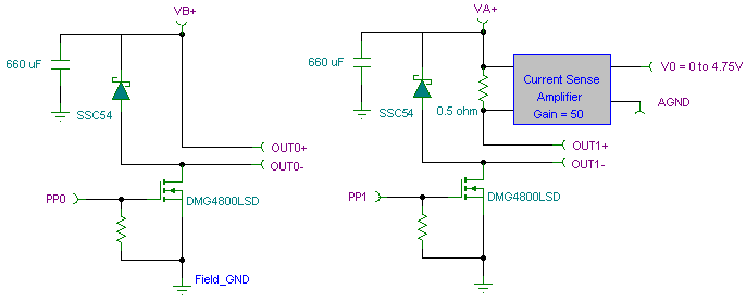
The PWM pulse width modulation controller board enables 9S12/HCS12 microcontrollers or PIC microcontrollers to output 8 channels, each capable of delivering 5 DC amps, while incorporating current sensing for the PWM waveform. This PWM driver circuit is suitable for...
A pulse counter can be constructed using a 7490 decade counter and a 7557A timer. This circuit is capable of counting from zero to nine. Pins 3 and 2 of all 7490s must be interconnected. The circuit utilizes the 7490...

A monostable multivibrator (MMV) features one stable state and one quasi-stable state. The circuit remains in its stable state until an external triggering pulse prompts a transition to the quasi-stable state. After a designated time period T, the circuit...
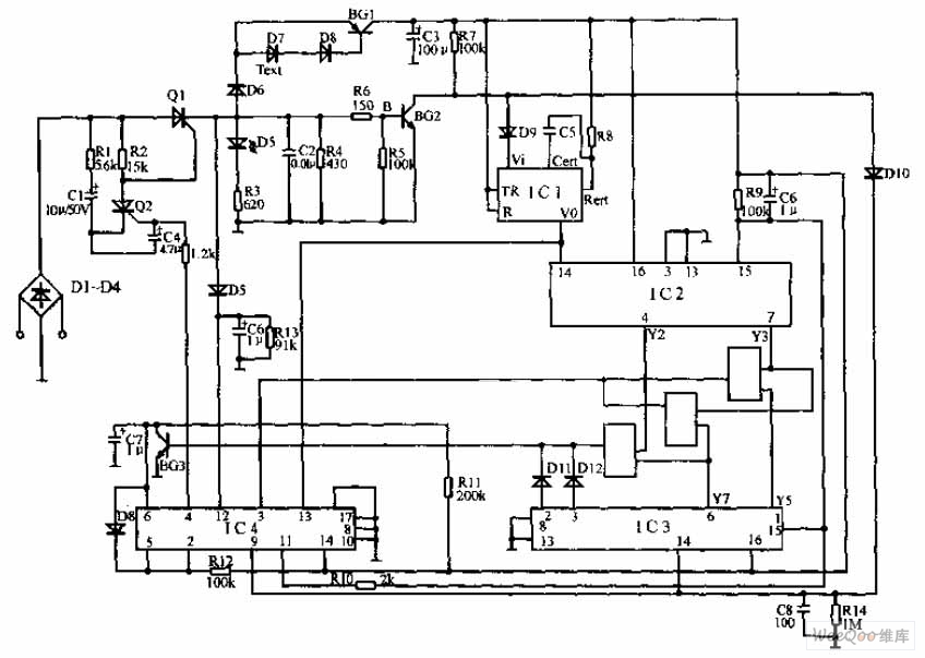
The pulse telephone 160 168 controller circuit is depicted above. This controller can be installed either on the telephone or on the switchboard of the trunk line. It effectively prevents unauthorized dialing of numbers 160 and 168. Diodes D1...

Communications between commercial aircraft and the ground can be intriguing, entertaining, and occasionally unsettling. However, radios that can receive the frequency range of approximately 220 MHz to 400 MHz, commonly utilized for both military and commercial aircraft, are not...