
Digital 7 Segment Pulse Counter
The circuit utilizes the 7490 decade counter, which is a versatile IC designed to count pulses in a decimal format. It can count from 0 to 9, providing a straightforward solution for applications requiring basic counting functionality. The 7557A timer, on the other hand, serves as a dual timer and can be configured in monostable or astable mode, allowing for precise timing intervals or pulse generation to drive the counting process.
To construct the pulse counter, the 7490 IC should be connected in such a way that its output can be utilized to display the counted value. The interconnection of pins 3 and 2 is crucial as it allows for the proper functioning of the counter. Pin 3 typically serves as the carry-out pin, while pin 2 is used for enabling the counting operation. By connecting these pins across multiple 7490 ICs, it is possible to cascade them for counting beyond the single IC's limit, although in this specific application, only a single IC is utilized for counting up to nine.
The 7557A timer can be configured to generate clock pulses at a desired frequency, which will serve as the input to the 7490 counter. The output of the 7490 can then be fed into a display mechanism, such as a 7-segment display or an LED array, to visually represent the counted values. Additional components, such as resistors and capacitors, may be required to set the timing characteristics of the 7557A, ensuring that the pulse rate is suitable for the counting application.
Overall, this pulse counter circuit offers a simple yet effective solution for counting applications, leveraging the capabilities of the 7490 and 7557A integrated circuits to achieve reliable and accurate counting from zero to nine.A pulse counter can be built by using 7490 decode counter and 7557A. This circuit can count from zero to 9. Pins 3 and 2 of all 7490`s must be connected.. 🔗 External reference
Related Circuits
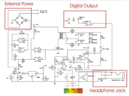
The basic Geiger counter circuit is similar to the previous version, with the addition of components for three optional enhancements: an external power input, a headphone jack, and a digital output, highlighted in red. The external power input is...
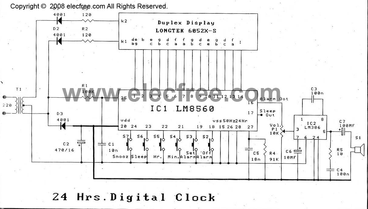
The digital time clock circuit is of great interest to electronic amateurs. The most popular clock ICs include the LM8361 and MM5387. Unfortunately, these ICs... The digital time clock circuit serves as an essential component for various electronic applications, providing...
Power the frequency counter and adjust the coarse (top pot) and fine (bottom pot) controls to display zero frequency. Turn the pots counter-clockwise to achieve a zero reading. Occasionally, the counter may show only squares without digits. If this...
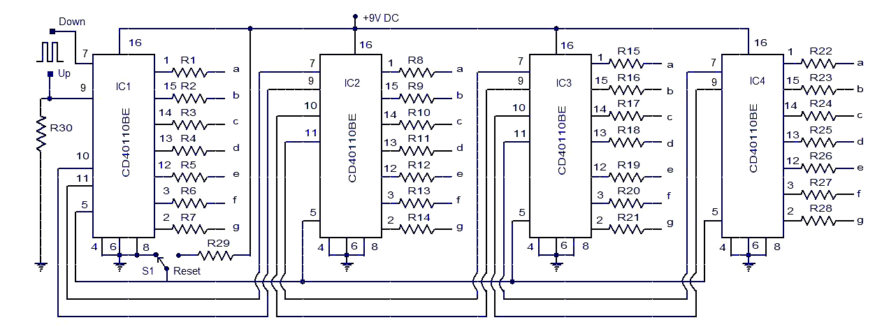
This circuit diagram illustrates a simple up/down counter suitable for various applications. It utilizes the CD40110BE IC, a CMOS decade up/down counter. Common cathode seven-segment displays are connected to the outputs of each IC. The display connected to IC1...
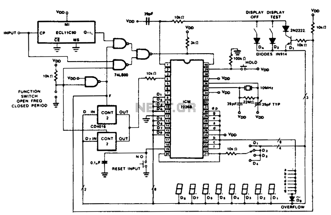
The figure illustrates the application of a CD4016 analog multiplexer to route digital outputs back to the FUNCTION input. The CD4016 functions as a digitally controlled analog transmission gate, eliminating the need for level shifting of the digital output....

The schematic for this project is visually acceptable, although it is not the most refined layout for a schematic. The basic flow progresses from left to right, starting with the state machine, followed by the 555 timers, then the...