
air craft receiver

This circuit design focuses on creating a straightforward and accessible receiver capable of tuning into the 220 MHz to 400 MHz frequency band used for aircraft communications. The schematic typically includes a few essential components: an antenna, a radio frequency (RF) amplifier, a mixer, and a demodulator.
The antenna, which is crucial for capturing the RF signals, should be designed to operate efficiently within the specified frequency range. A dipole antenna or a quarter-wave monopole antenna can be effective choices, depending on the desired portability and ease of construction.
The RF amplifier is responsible for boosting the weak signals received by the antenna. A low-noise amplifier (LNA) is often used to enhance the signal strength without significantly adding noise, ensuring that the subsequent stages of the circuit receive a clear signal.
Next, the mixer combines the amplified RF signal with a local oscillator signal to convert the frequency of the incoming signal to a lower intermediate frequency (IF). This process allows for easier filtering and demodulation. The choice of the local oscillator frequency is critical, as it determines the tuning capabilities of the receiver.
The demodulator then extracts the audio information from the IF signal. A simple envelope detector can be employed for amplitude modulation (AM) signals, which are commonly used in aircraft communications. If frequency modulation (FM) is utilized, a dedicated FM demodulator circuit may be necessary.
Finally, the output can be connected to a speaker or headphones, allowing users to listen to the communications. Additional components such as variable resistors can be included in the circuit to adjust the volume and improve user experience.
In conclusion, this circuit provides an accessible means for enthusiasts to engage with aircraft communications, making it a valuable project for hobbyists interested in radio technology. Proper construction and tuning of the circuit will ensure optimal performance and enjoyment.The communications between commercial aircraft and the ground can be interesting, amusing and sometimes even disturbing. However radios that receive the approximately 220MHz to 400MHz band commonly used for aircraft (both military and commercial) are not easily found.
And scanners can be complicated, large and expensive. With an easy to build circ uit such as this one, everyone can enjoy listening in on these conversations. 🔗 External reference
Related Circuits

By adding one integrated circuit and some passive components, the previously developed 40-meter direct conversion receiver design has been transformed into a superheterodyne model. The advantages of single signal reception in this circuit are particularly appreciated by those who...
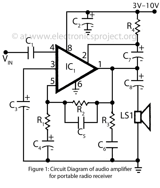
This is a simple audio amplifier circuit built around the BEL1895 1W audio amplifier integrated circuit (IC). This circuit serves as an alternative to more complex audio amplifier circuits designed for portable radio receivers. It does not require a...
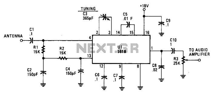
This simple AM circuit utilizes a 561B. It lacks an inductance/capacitance tuning circuit, as the 365 pF capacitor connected between pins 2 and 3 is responsible for all tuning. A good external antenna and a solid ground connection are...

The 10K resistor is necessary if the receiver is to mute (squelch) under no-signal conditions. An additional 100K resistor can be added in series with this resistor to create an adjustable squelch. This circuit is designed to drive a...
Before proceeding with these steps, ensure that the software calibration and the basic procedures for checking audio circuit components have been completed. The audio circuit schematic diagram is preferred for easy tracking, and this method will aid in future...

Two CA3130 operational amplifiers are utilized, with one functioning as a multivibrator and the other serving as a hysteresis switch. Additionally, a CA3160 amplifier is employed as a linear staircase generator. The circuit incorporates three BiMOS operational amplifiers. The circuit...