
Pulse Delay Generator

The delayed pulse generator circuit is designed to produce a pulse output after a specified delay, allowing for precise timing control in various applications. This circuit typically employs a combination of resistors, capacitors, and a timing component such as a 555 timer IC or a microcontroller to achieve the desired delay and pulse characteristics.
The operation begins with the charging of a capacitor through a resistor, which determines the delay period. The time constant, defined by the product of the resistor (R) and capacitor (C) values (τ = R × C), dictates how long it takes for the capacitor to reach a certain voltage level, triggering the output pulse. Once the voltage across the capacitor exceeds a predefined threshold, the output transitions from low to high, generating the pulse.
Additionally, the pulse width can be adjusted by modifying the resistor and capacitor values, allowing for independent control over the pulse rate and duration. This flexibility makes the delayed pulse generator suitable for applications such as timing circuits, signal modulation, and as a trigger for other electronic devices.
In practical implementations, the circuit may include features such as adjustable delay settings, output indicators, or protection components to enhance reliability and user interaction. Overall, the delayed pulse generator is a versatile component in electronic design, providing essential timing functions across a wide range of systems.This circuit is a Delayed Pulse Generator that is used to provide pulse rate and independent control of initial delay. The pulse generator of this circuit is. 🔗 External reference
Related Circuits
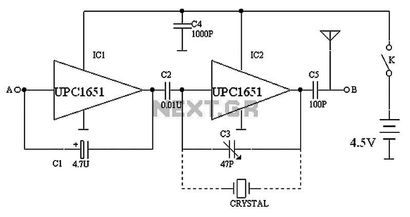
The circuit depicted in the figure includes IC1 and C1, which form a low-frequency oscillator operating at approximately 400 Hz. IC2 and C3 are configured to create a frequency oscillator around 37 MHz. The low-frequency signal is output from...
The hobby circuit described utilizes a unique method to generate approximately 12,000 volts with a current of about 5 microamperes. It employs two silicon-controlled rectifiers (SCRs) that form two pulse generator circuits. These SCRs discharge a 0.047 microfarad, 400-volt...
An ultrasonic sound wave can be generated using an electronic circuit. This simple electronic circuit can generate an ultrasonic wave with a frequency range of 12 kHz and above. The electronic circuit designed for generating ultrasonic sound waves typically utilizes...

Two CA3130 operational amplifiers are utilized, with one functioning as a multivibrator and the other serving as a hysteresis switch. Additionally, a CA3160 amplifier is employed as a linear staircase generator. The circuit incorporates three BiMOS operational amplifiers. The circuit...
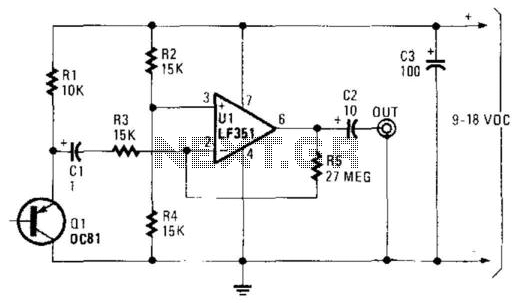
A germanium transistor (Ql) is utilized as a noise generator within the audio frequency range. The operational amplifier (Ul) serves as a high-gain amplifier. The specific characteristics of Ql are not critical; most germanium transistors are generally effective for...
After completing several V-USB tutorials, the next project undertaken was to create a compact USB HID keyboard device that types a password stored in EEPROM each time it is connected. The password can be regenerated by pressing the CAPS...
Warning: include(partials/cookie-banner.php): Failed to open stream: Permission denied in /var/www/html/nextgr/view-circuit.php on line 713
Warning: include(): Failed opening 'partials/cookie-banner.php' for inclusion (include_path='.:/usr/share/php') in /var/www/html/nextgr/view-circuit.php on line 713