
Simple Ultrasonic Wave Generator
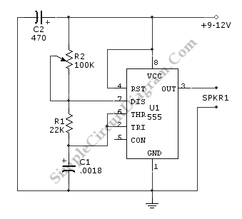
The electronic circuit designed for generating ultrasonic sound waves typically utilizes an oscillator, which is responsible for producing a high-frequency signal. In this case, the frequency range specified is from 12 kHz and can extend to several hundred kHz, depending on the components used and the desired application.
The core of the circuit often includes a timer IC, such as the 555 timer, configured in astable mode to produce a continuous square wave output. This square wave is then fed into a transistor circuit that acts as a switch, amplifying the signal to drive an ultrasonic transducer. The transducer, often made of piezoelectric materials, converts the electrical signal into mechanical vibrations, producing ultrasonic sound waves.
Additional components may include resistors and capacitors to set the frequency of oscillation and stabilize the circuit's performance. Proper selection of these components is crucial to achieving the desired frequency and ensuring that the output signal is clean and free of distortion.
For applications such as pest control, ultrasonic cleaning, or distance measurement, the characteristics of the generated ultrasonic waves can be tailored by adjusting the circuit parameters. The circuit may also include a variable resistor or potentiometer to allow for fine-tuning of the frequency output.
In summary, this electronic circuit for generating ultrasonic sound waves is a straightforward design that leverages basic electronic components to produce high-frequency sound suitable for a variety of applications.Ultrasonic sound wave can be generated using electronic circuit. This simple electronic circuit can generate an ultrasonic wave with frequency range of 12 to . 🔗 External reference
Related Circuits
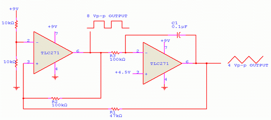
The ratio R1/R2 determines the amplitude of the triangle wave in relation to the square-wave output. The frequency of oscillation for both waveforms can be calculated using the equation: fo = 1/(4R3C1) * (R2/R1). In this circuit, R1 and R2...
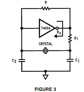
To generate a 1 MHz square wave, it is advisable to use a higher frequency crystal and divide it down for two reasons: (1) 4 MHz crystals are generally more affordable and easier to procure than 1 MHz crystals;...
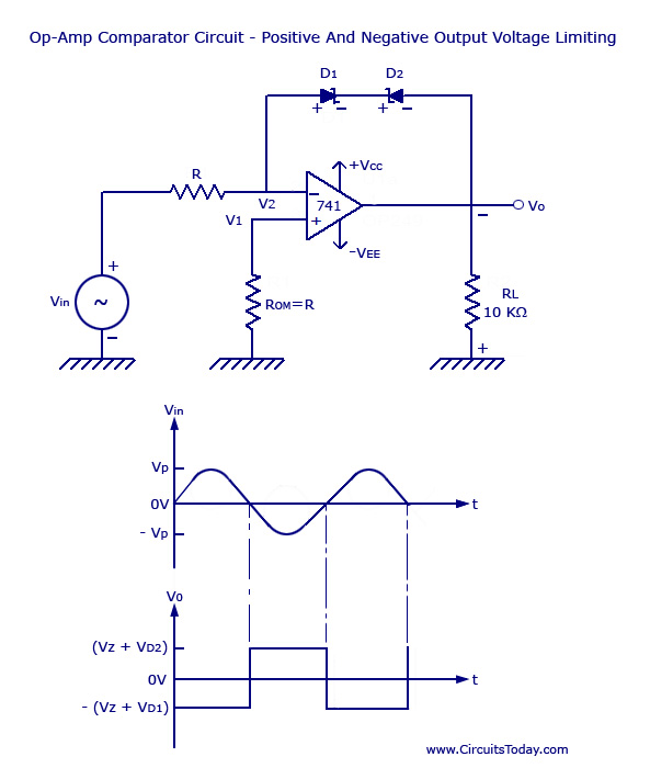
Voltage Limiter Circuit Using Op-amp - Circuit Diagram, Waveform, Positive and Negative Voltage Limiters. The voltage limiter circuit utilizing an operational amplifier (op-amp) serves to restrict the output voltage to predefined levels, effectively preventing it from exceeding or falling below...
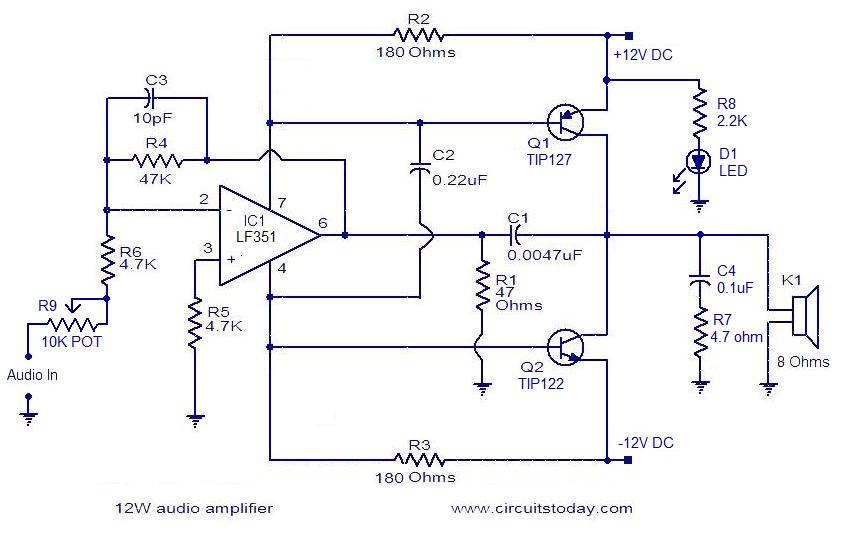
The circuit presented is a simple audio amplifier capable of delivering 12W to an 8 Ohm speaker. The operational amplifier IC TL081 serves as the preamplifier in this design. Alternatively, any operational amplifier with compatible power supply ratings can...
The apparatus consists of a cavers point detection circuit and a triggering display circuit. The cavers instrument functions as a test probe, which, when held in one hand, can detect acupuncture points by touching the skin with another probe....
In Japan, the household electricity operates at either 50 Hz or 60 Hz. For a frequency of 50 Hz, one complete sine wave occurs 50 times in one second, while at 60 Hz, it occurs 60 times. Lissajous figures...