
Multipurpose tape recorders TV signal generator circuit
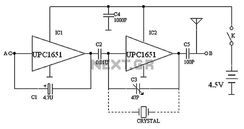
The circuit design incorporates two primary oscillators, a low-frequency oscillator and a high-frequency oscillator, which work in tandem to modulate signals for transmission. The low-frequency oscillator, composed of IC1 and C1, is responsible for generating a stable 400 Hz signal, which can be utilized for various audio applications or as a reference frequency in other circuits. The output from this oscillator is routed through C2, which serves as a coupling capacitor, allowing the low-frequency signal to pass while blocking any DC components.
On the other hand, the high-frequency oscillator, formed by IC2 and C3, operates at 37 MHz. This oscillator is crucial for modulating the low-frequency signal onto a higher frequency carrier wave, enabling efficient transmission over antennas. The design includes provisions for harmonic reception, allowing the circuit to pick up signals from the high-frequency oscillator or other channels, which is particularly useful for television signals. The presence of harmonics can lead to the reception of multiple channels, resulting in the observed black-and-white striped signals on the television display.
Points A and B in the circuit serve as output terminals for detecting the respective low-frequency and image channel signals. This dual output capability enhances the circuit's versatility, allowing it to be used in a variety of applications, including signal processing and television reception.
Furthermore, the design allows for the substitution of C3 with a quartz crystal, which can significantly improve the frequency stability of the oscillator. The circuit provides flexibility in selecting different crystal frequencies, making it adaptable for various applications such as tape recorders and television IF signal sources. By changing the crystal, users can easily switch between frequencies like 465 kHz, 10.7 kHz, 6.5 kHz, 4.43 MHz, and the original 37 MHz, further enhancing the circuit's functionality and performance in signal modulation and reception tasks. Circuit shown in Figure, IC1, C1 composition 400HZ about low frequency oscillator; IC2, C3 composed around 37MHZ frequency oscillator; low-frequency signal from the output C2 o f the high-frequency signal is modulated. C4 antennas and transmission system. Harmonics can receive high-frequency oscillator (or other channels) in the three TV channels showed black and white stripe signal. A point, B point output signal, respectively, for the detection of low-frequency signal and image channel.
The C3 can replace quartz crystal oscillation frequency stability, as shown in dotted lines in FIG. If the access point using a terminal C3 or socket, respectively, into the C3 crystal; frequency is selected 465KHZ, 10.7KHZ, 6.5KHZ, 4.43MHZ, 37MHZ can do tape recorders, television IF signal source.
Related Circuits
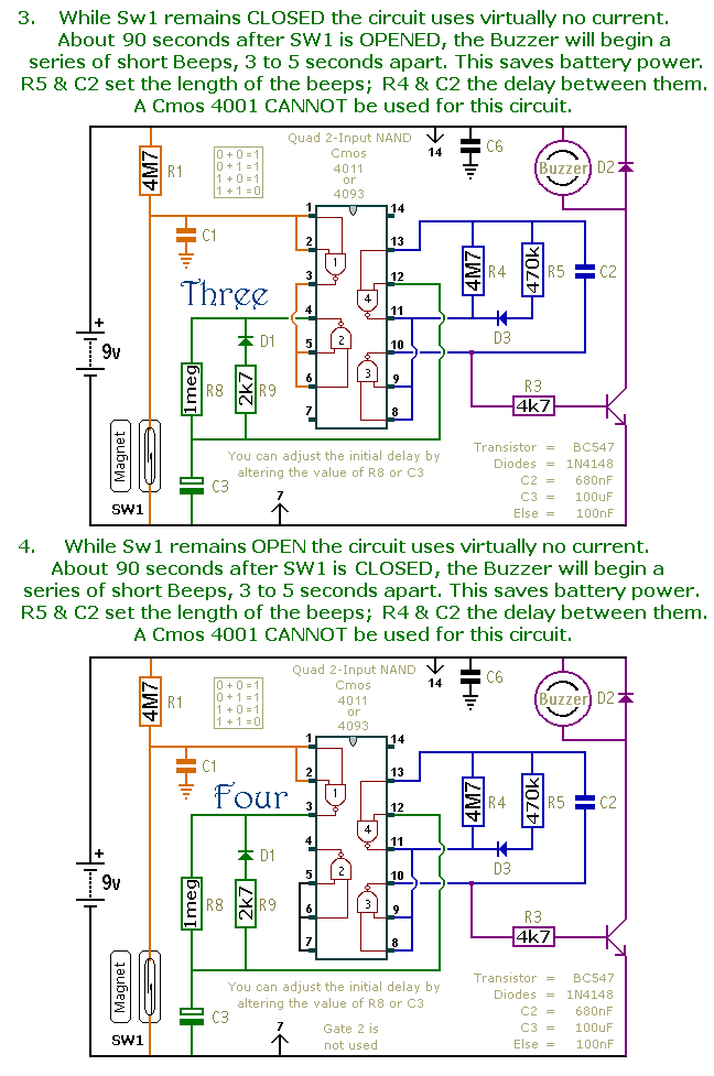
This is a collection of compact, self-sufficient alarm circuits designed for low standby current, making them ideal for battery operation. Some circuits are activated by normally-open and normally-closed switches, while others respond to variations in light or temperature. This...
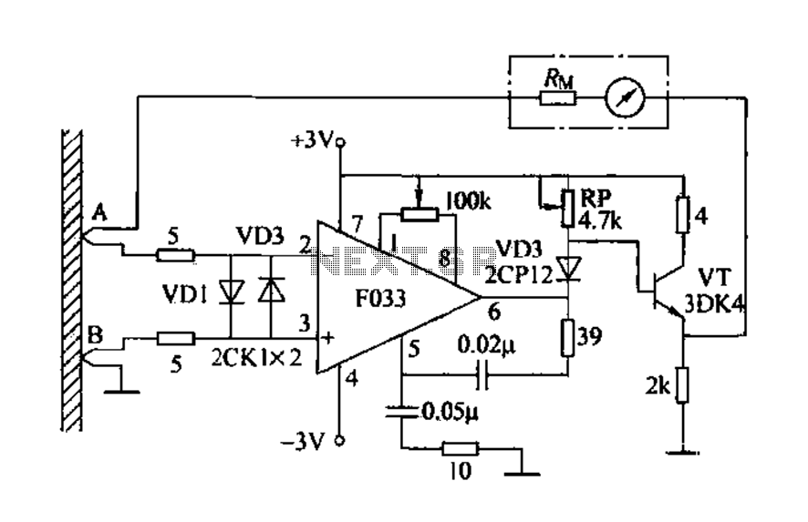
Detecting electrical equipment sometimes requires disconnecting the circuit in series for more accurate measurements of electrical current using an ammeter. However, restoring the circuit to its original state is necessary, as it can affect the normal operation of electrical...
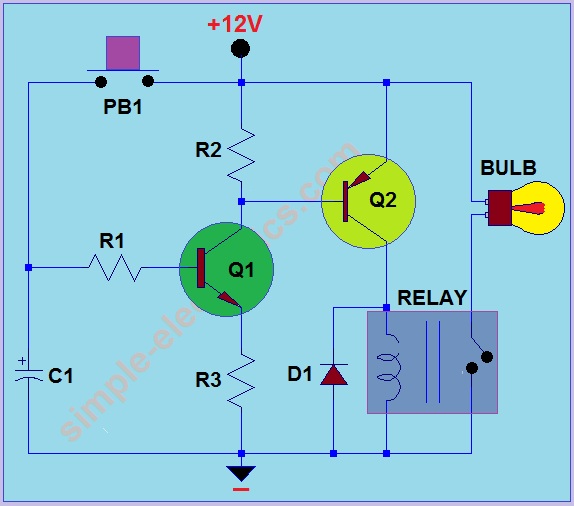
This circuit operates by activating a headlight when the push-button PB1 is pressed. The headlight remains illuminated for a predetermined duration, which can range from several seconds to minutes, before automatically turning off. When PB1 is engaged, capacitor C1...
This AC drill speed controller circuit schematic allows for the control of the drilling speed of a borer or drilling machine. This project is based on the principle that... The AC drill speed controller circuit is designed to modulate the...

The circuit is constructed using the ICM7217 integrated circuit from Intersil, which features a CMOS up/down counter with a four-digit display. The clock generator circuit, IC3, produces a square wave clock signal with a period of one second, available...
The circuit depicted is designed to protect a system from power supplies that may exceed safe limits. An example of this is small consumer products that utilize external AC adapters, where there is a risk of accidentally connecting the...