
Pulse generator

In this circuit, the duty cycle of the output pulse is determined by the resistor values R4 and R5. The formula R4/(R4 + R5) x 100% indicates that the duty cycle is a percentage of the total resistance in the circuit, specifically focusing on R4's contribution relative to the sum of R4 and R5. This relationship highlights the importance of selecting appropriate resistor values to achieve the desired pulse characteristics.
When the duty cycle is less than 50%, the diode D1 can be omitted from the circuit. This simplification may be advantageous in specific applications where a lower duty cycle is required, allowing for increased efficiency by reducing the number of components. In such cases, it is recommended to increase the value of R2 to maintain the desired performance of the circuit.
Furthermore, the distinction between R4(eff) and R4(actual) plays a crucial role in understanding the circuit's behavior. R4(eff) represents the effective resistance that influences the duty cycle, while R4(actual) refers to the physical resistor value implemented in the circuit. It is essential to note that R4(actual) will always be greater than R4(eff), ensuring that the actual duty cycle remains consistent with the theoretical calculations. This characteristic must be taken into consideration during the design process to achieve optimal circuit performance.The duty cycle Of the output pulse is equal to R4/(R4 + R5) x 100%. For duty cycles of less than 50%, Dl can be eliminated and R2 raised R4(eff) is the effective value of R4 in the circuit and R4(actual) is the actual value used; R4 (actual) will always be larger than R4(eff).
Related Circuits
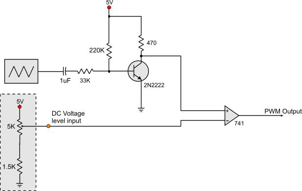
Circuits that generate PWM pulses typically translate a resistor value into a change in duty cycle. While this method is convenient, there are instances where a voltage-controlled PWM generator is required. Although microcontrollers can produce a variety of PWM...
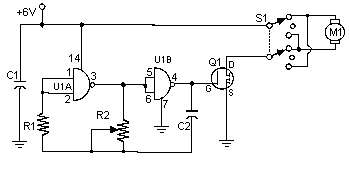
Often, people attempt to control DC motors with a variable resistor or variable resistor connected to a transistor. While the latter approach works well, it generates heat and hence wastes power. This simple pulse width modulation DC motor control...
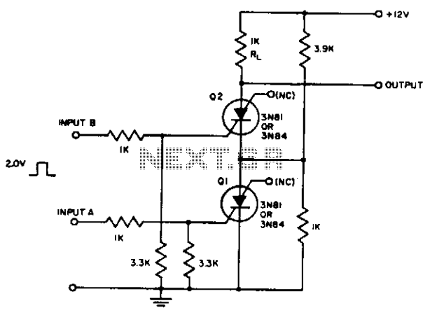
The resistor divider connected between Q1 and Q2 supplies IH to Q1 after input A triggers it. It also prevents the input from triggering Q2 until Q1 conducts. Consequently, the first input pulse after input A is applied will...
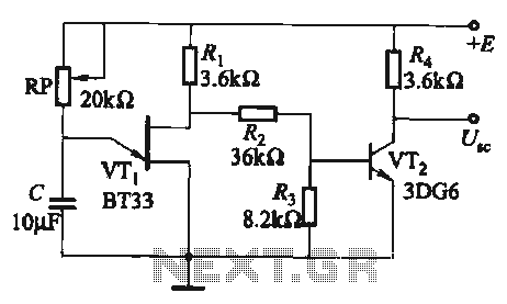
The circuit comprises a single-junction transistor VTi, a resistance Ri, a potentiometer RP, and a capacitor C, forming a relaxation oscillator and an amplifier transistor VTz. The adjustment potentiometer RP allows for changing the relaxation oscillation frequency, providing a...

The ramp generator serves as a cost-effective alternative to commercial function generators, offering a more linear and repeatable output compared to traditional analog integrators. This circuit produces a triangle waveform in burst mode, generating two cycles of 10.24 ms...
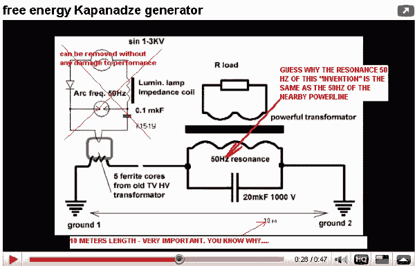
An inventor from the Republic of Georgia, Tariel Kapaladze, claims to have developed a 5-kilowatt free energy generator. In a demonstration video, the device seemingly produces large amounts of energy without any visible source. While it appears to extract...