
Pulse sequence detector

In this circuit configuration, a resistor divider is utilized to control the operation of two transistors, Q1 and Q2. The resistor divider is strategically placed between the two transistors, ensuring that Q1 receives the necessary bias current (IH) once input A is activated. This configuration is critical as it establishes a sequential operation where Q1 must conduct before Q2 can be triggered.
Upon the application of input A, Q1 begins to conduct, allowing current to flow through the load resistor, RL. The significance of this sequence is that it prevents Q2 from being activated prematurely, which could lead to undesired circuit behavior. The design ensures that the output from Q1 is stable before any action is taken by Q2, thereby enhancing the reliability of the circuit operation.
The resistor divider's values must be chosen carefully to ensure that the correct voltage and current levels are provided to Q1 while also maintaining a high enough voltage to keep Q2 in an off state until Q1 is fully operational. This method of controlling transistor operation through a resistor divider is a common technique in electronic circuit design, ensuring that multiple components can operate in a coordinated manner without interference or undesired triggering.
Moreover, the load resistor RL plays a crucial role in determining the overall performance of the circuit. It is responsible for limiting the current flowing through the circuit and ensuring that the transistors operate within their specified limits. The choice of RL will directly affect the voltage drop across Q1 and the overall efficiency of the circuit.
In summary, this circuit design highlights the importance of sequential control in multi-transistor configurations, ensuring that the operation of one component is dependent on the successful activation of another, thereby preventing potential faults and enhancing circuit stability.The resistor divider connected between Ql and Q2 supplies IH to Ql after input A triggers it. It also prevents input from triggering Q2 until Ql conducts. Consequently, the first input pulse after input A is applied will supply current to RL.
Related Circuits
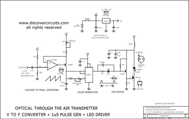
This circuit receives the signal from the amplifier and emits powerful 1μs infrared light pulses from a low-cost LED, which are frequency modulated by the audio information. The 10kHz center frequency of the pulse stream is sufficiently low, allowing...
The PTB78560x is a series of 30 W rated isolated DC/DC converters designed to operate from a standard 24 V or 48 V telecom central office (CO) supply. Housed in a 12 package, each model features a wide adjustable...
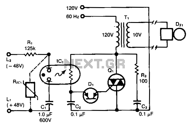
This ring detector, utilizing a neon-LDR (light-dependent resistor) optocoupler, simplifies interfacing with telephone lines. The ring detector circuit is designed to detect the ringing signal from telephone lines, which typically operates at a frequency of 20 Hz to 25 Hz...
This circuit relies upon the extra high input impedance of a FET, and also demonstrates the gate terminals sensitivity to changes in voltage. The gate terminal here is left open circuit, connected only to the "probe" this being just...
This circuit is designed to indicate, via a flashing LED, when room noise exceeds a predetermined threshold. The thresholds are set at three fixed levels: 50 dB, 70 dB, and 85 dB. Two operational amplifiers (op-amps) are utilized to...
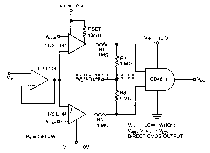
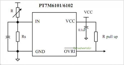
The detector utilizes three sections of an L144 and a DC4011 type CMOS NAND gate to create a very low power voltage monitor. If the input voltage, Vin, is above Vhigh or below Vlow, the output will be a...