
Pulse Generator With Variable Duty Cycle Circuit
This reference voltage, in conjunction with the triangular waveform, is applied to the positive and negative inputs of comparator ICD, respectively. The trip voltage of the comparator can be set at any point along the triangular waveform, causing the output of IOD to change at that point. Adjusting the reference voltage modifies the duty cycle of the comparator's output by varying the potentiometer at the negative input of the integrator, thus changing the integration time without affecting the duty cycle.
The pulse generator circuit is designed for versatility and precision in generating pulse signals. The frequency range of 400 to 4000 Hz allows for a wide array of applications, from audio signal generation to timing applications in digital circuits. The adjustable duty cycle is critical for applications that require specific pulse widths, such as in PWM (Pulse Width Modulation) control systems.
The triangular waveform produced by the integrator is essential for the operation of the comparator, as it provides a linear ramp that can be compared against the variable reference voltage. The choice of a 100-kΩ potentiometer for setting the reference voltage ensures that the circuit can be easily tuned for specific requirements. The feedback network in ICA is crucial for ensuring stable oscillation, as it maintains the necessary conditions for the switching behavior of the circuit.
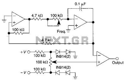
The output from the comparator (IOD) can drive various loads, making this pulse generator suitable for interfacing with other digital or analog circuits. The simple architecture, comprising a single IC and passive components, facilitates easy integration into larger systems while minimizing the component count and associated costs. This design exemplifies efficient engineering practices in electronic circuit design, balancing functionality with simplicity. Using only one IC and six passive components, this pulse generator has a frequency range of 400 to 4000 Hz and an adjustable duty cycle of 1 to 99%. A threshold detector (ICA) and an integrator (ICB) generate a triangular waveform. A positive voltage at the output of ICA causes the output of ICB to become a negative-going ramp. When the output of this ramp reaches a certain value, ICA, by virtue of its positive-feedback network, changes state; its output becomes negative, and the integrator generates positive ramp.
This process continually repeats. A voltage follower (ICC) and a 100-kn potentiometer provide a variable 0.18-V reference voltage. This reference voltage, along with the triangular waveform, feeds into the positive and negative inputs, respectively, of comparator ICD. You can set the comparator`s trip voltage at any point on the triangular waveform; IOD`s output changes at that point.
Varying the reference voltage alters the duty cycle of the comparator`s output by adjusting the potentiometer at the negative input of the integrator, thereby varying the integration time without altering the duty cycle. 🔗 External reference
Related Circuits
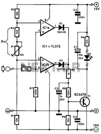
Two operational amplifiers are utilized as comparators to signal an excessive magnitude of an audio frequency (AF) signal, regardless of whether the signal is positive, negative, or asymmetrical. A reference voltage is established for both operational amplifiers using a...
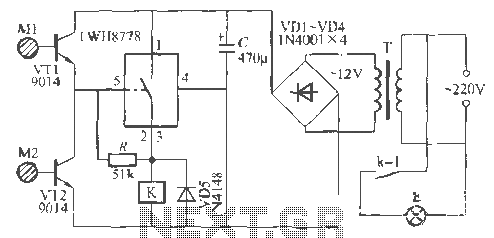
The Rw A77S power system utilizes an integrated circuit fabrication design featuring a dual touch light switch. It employs a transformer (T) for power conversion, a rectifier (VD4), and a capacitor (C) for filtering, resulting in a 12V DC...
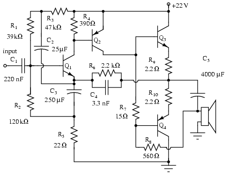
Note that Q3 and Q4 in the figure below are complementary, with Q3 being an NPN transistor and Q4 being a PNP transistor. This circuit is suitable for moderate power audio amplifiers. For a detailed explanation of this circuit,...
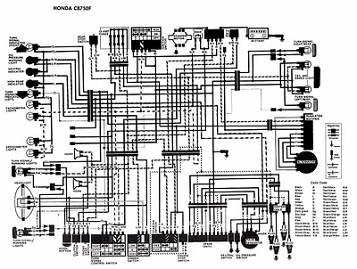
The following image illustrates the electrical wiring connection diagram for the Honda Motorcycle CB750F. It details the connections between various Honda components, including the right turn signal indicator light, oil pressure warning light, neutral indicator, high beam indicator, turn...
A discussion took place on synth-diy regarding the challenges of constructing a voltage-controlled oscillator with a sawtooth wave output, where the duty cycle (the ratio of ramp-up time to ramp-down time) can be adjusted using a separate control voltage....
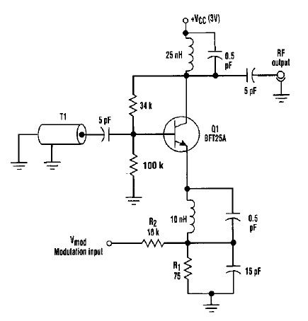
This varactorless high-frequency modulator electronic project must be powered by a simple DC 3-volt power source, such as a 3-volt battery. Traditionally, high-frequency oscillators are frequency-modulated using a varactor. However, varactors typically require a significant voltage change to achieve...