
Amplifier circuits
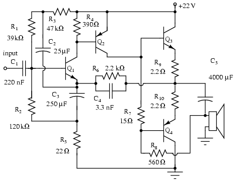
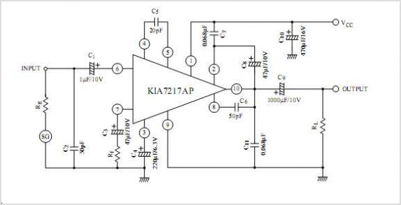
The described circuit utilizes a complementary push-pull configuration, which is commonly employed in audio amplifier designs to enhance efficiency and reduce distortion. In this setup, Q3 (NPN) and Q4 (PNP) transistors work together to amplify the audio signal. The complementary nature of these transistors allows for both halves of the audio waveform to be amplified, which is critical for maintaining signal integrity and achieving high fidelity in audio applications.
The circuit typically includes biasing resistors that ensure the transistors operate in their active regions, minimizing crossover distortion that can occur when transitioning between the two transistors. Additionally, feedback mechanisms may be implemented to stabilize the gain and improve linearity across a range of frequencies.
Power supply considerations are also crucial; the circuit must be designed to handle the required voltage and current levels for moderate power output, ensuring that the transistors remain within their safe operating areas. Heat dissipation must be managed effectively, often through the use of heat sinks, to prevent thermal runaway and ensure reliable long-term operation.
Overall, this complementary push-pull amplifier configuration is a robust solution for moderate power audio amplification, providing a good balance between performance, efficiency, and thermal management.Note, Q3 and Q4 in Figure below are complementary, NPN and PNP respectively. This circuit works well for moderate power audio amplifiers. For an explanation of this circuit see Direct coupled complementary-pair, Ch 4. 🔗 External reference
Related Circuits
This power supply was designed for use with the Simple hybrid amplifier published elsewhere in this issue. It is suitable for various applications as well. A cascade generator is utilized for the 170 V output, a switch-mode supply provides...
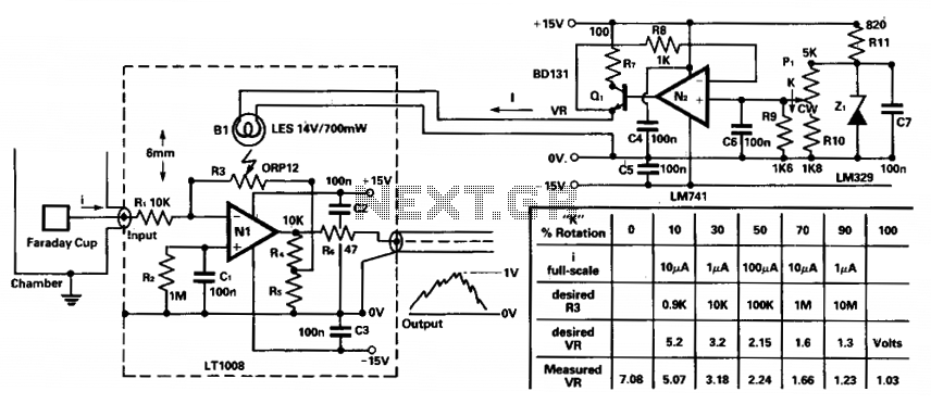
To amplify small current signals, such as those from an electron collector inside a vacuum chamber, it is beneficial for reasons related to noise and bandwidth to utilize a "head amplifier" connected to the chamber. The operational amplifier N1...
The TDA7294 amplifier module is a monolithic integrated circuit designed for use as an audio class AB amplifier in hi-fi applications. It has a wide voltage range and output current capability, enabling it to supply the highest power into...

The circuit employs a field-effect transistor (FET) at the input of a Schmitt trigger, allowing the use of a low-value capacitor. The trigger, controlled by Q1 and O2, exhibits a hysteresis of approximately 3V, regulated by a 3V zener...
This circuit turns off an amplifier or any other device when a low-level audio signal fed to its input is absent for 15 minutes at least. Pushing P1, the device is switched on, feeding any appliance connected to SK1....
The UTC L2572 is a wideband PLL FM demodulator designed primarily for use in satellite tuners. It incorporates all essential components, except for the loop feedback elements, to create a complete PLL system capable of operating at frequencies up...
Warning: include(partials/cookie-banner.php): Failed to open stream: Permission denied in /var/www/html/nextgr/view-circuit.php on line 713
Warning: include(): Failed opening 'partials/cookie-banner.php' for inclusion (include_path='.:/usr/share/php') in /var/www/html/nextgr/view-circuit.php on line 713