
Varactorless high frequency modulator circuit design electronic project
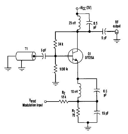
The varactorless high-frequency modulator circuit is designed to operate efficiently at low voltage levels, making it suitable for battery-powered applications. The use of base-charging capacitance modulation allows for effective frequency modulation without the complexity and limitations associated with varactor diodes. In this configuration, transistor Q1 serves as the active element, where its collector current is modulated by an external voltage signal (Vmod) applied through resistor R2. This modulation alters the effective capacitance at the base of Q1, which in turn influences the oscillation frequency of the circuit.
The transmission line T1, being a quarter-wave design, plays a crucial role in determining the resonant frequency of the oscillator. Its characteristics, including low-loss and high-quality materials, ensure that the oscillations are stable and sustained. The interaction between the negative resistance seen at the base of Q1 and the transmission line is essential for maintaining continuous oscillation. The circuit's design must ensure that the terminal impedances are correctly matched to optimize performance and achieve the desired frequency response.
Overall, this varactorless high-frequency modulator represents an innovative approach to frequency modulation, leveraging base-charging capacitance modulation to overcome the limitations of traditional varactor-based designs. The simplicity of the power requirements, along with the efficiency of the circuit, makes it a valuable solution for various applications in the field of electronics.This varactorless high frequency modulator electronic project, must be powered from a simple DC 3 volt power source ( you can use a 3 volt battery). Traditionally, high-frequency oscillators are frequency-modulated by using a varactor. However, varactors usually require a large voltage change to achieve a reasonable capacitance change ; a problem
in many battery-powered systems. Such a problem can be overcome by employing base-charging capacitance modulation. Resistor R1 establishes Ql`s current, and R2 allows control of the collector bias current by Vmod. The transmission line (T1) in the negative resistance type oscillator determines the frequency of oscillation. T1 is a high-quality, low-loss, ceramic coaxial shorted quarter-wave transmission line. Under proper terminal impedances, a negative resistance is "seen" at Ql`s base. T1 reacts with this negative resistance to produce sustained oscillations, Frequency modulation is accomplished by changing Q1`s collector bias current and thus changing Ql`s base-charging capacitance.
This effect is "seen" at Ql`s base and causes a frequency shift in the resonators quarter-wave node. 🔗 External reference
Related Circuits
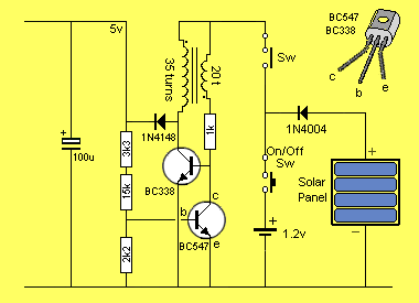
Powered by a solar panel, the circuit provides a 5V pure regulated DC voltage. It consists of an oscillator transistor and a regulator transistor. The solar panel charges the battery when sunlight is sufficient to generate a voltage above...
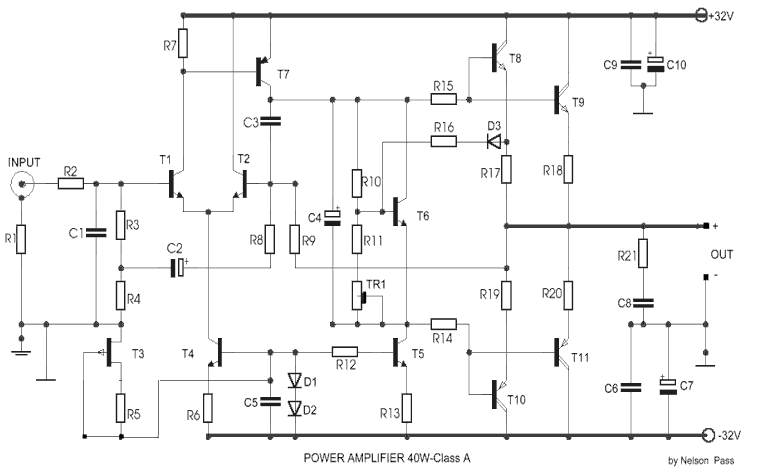
This is an audio power amplifier that delivers 40 W at 8 ohms in Class A operation. The power transistors are continuously active, enabling a substantial current to flow. The audio power amplifier described operates in Class A mode, which...
This is a kHz sine wave generator circuit built based on the configuration of an inverted Wien bridge (see C1-R3 C2-R4). R5 and R7 are used for output amplitude setting. Set R5 to read 1V RMS on an audio...
Have you ever accidentally left your front door ajar and had a pet escape? Here is a smart solution to this problem. The circuit is relatively simple but serves as a great example of using a compact circuit to...
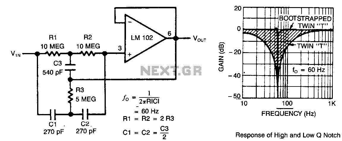
This circuit illustrates a twin-T network connected to an LM102 to form a high-Q, 60-Hz notch filter. The junction of R3 and C3, which is typically grounded, is bootstrapped to the output of the follower. Due to the low...
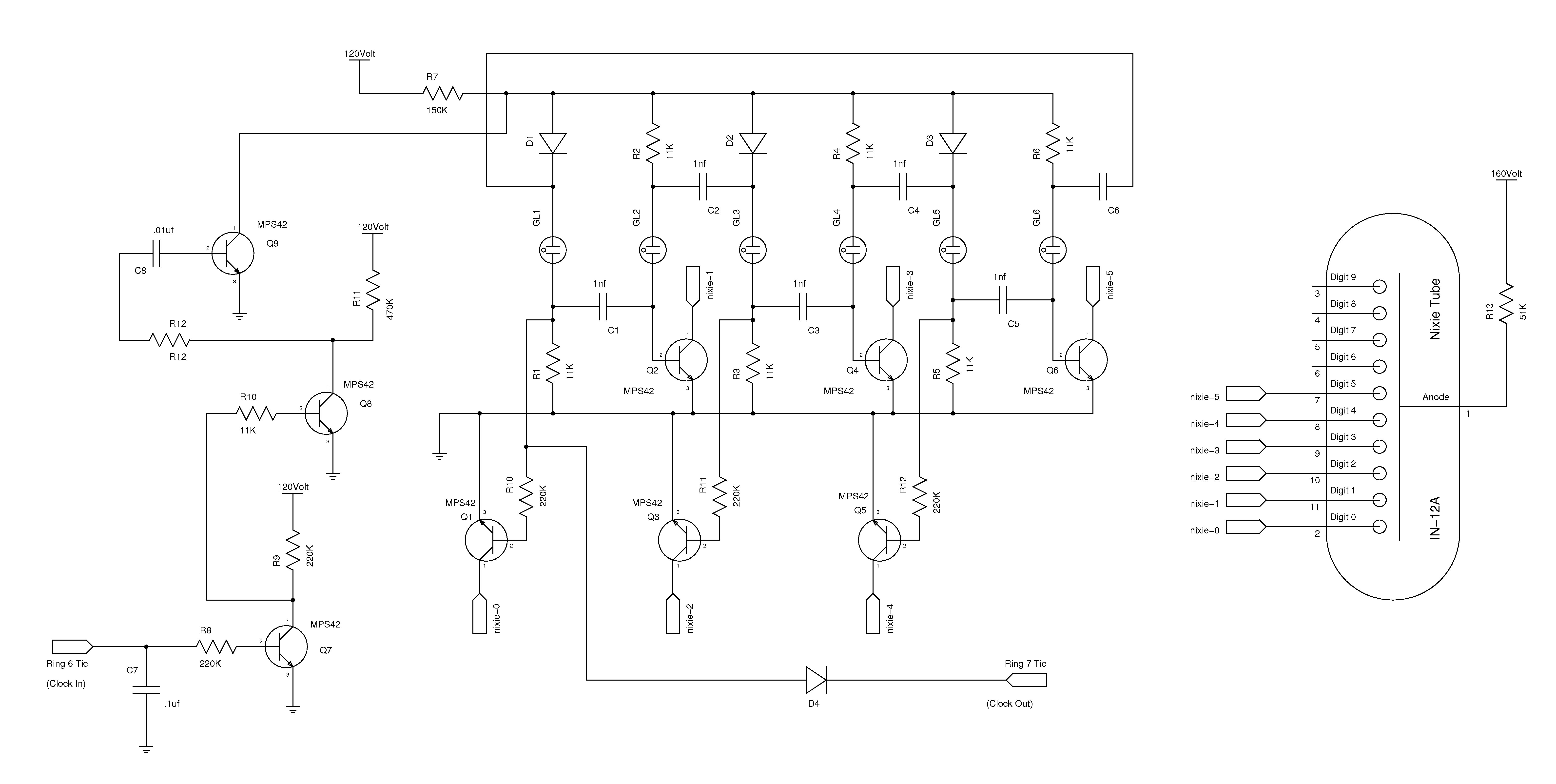
The nixie tube clock consists of a high-voltage power supply, seven ring counters, and an Atmel AVR processor. The power supply is shown in Schematic 1. It takes 12 volts AC and converts it to DC, which drives the...