
Pulse Operation of DC Solenoids

The described circuit operates on a pulse modulation technique, which is advantageous for solenoid control applications. The initial high voltage pulse energizes the solenoid, allowing for rapid actuation. The subsequent reduction in voltage to a lower holding level minimizes power consumption and reduces thermal stress on the solenoid, thereby prolonging its lifespan. The design utilizes a half-wave rectifier, which is a cost-effective solution for converting AC to DC, making it suitable for applications where high precision in voltage regulation is not critical.
The selection of components is crucial for optimal performance. The resistor R is not only responsible for limiting the holding current but also plays a significant role in the voltage drop across the solenoid when it is energized. The capacitor C must be chosen carefully to ensure that it can store sufficient energy to maintain the solenoid's magnetic field during operation. The empirical determination of capacitance values is essential, as variations in solenoid design and application requirements can lead to different energy storage needs.
The recovery time of the circuit, governed by the R-C time constant, is a critical factor in determining the maximum operating frequency of the solenoid. It is imperative to ensure that the capacitor can recharge in a timely manner to allow for successive operations without delay. The design should account for the maximum expected actuation frequency to ensure reliable performance in practical applications.
In summary, this pulse operation circuit for solenoids offers a robust solution for applications requiring efficient energy use and rapid actuation. Careful selection of resistors and capacitors, along with consideration of the recovery time, will ensure that the system operates effectively within its intended parameters.With pulse operation, the solenoid is energized momentarily with five to six times its rated voltage, then held in with less than half of its rated voltage. Application time is reduced drastically and the reduced holding voltage produces less arcing when the circuit is opened.
Additionally, a well regulated d-c power supply is not required. With switch S open, capacitor C charges to the line voltage value, VL. If a 24vdc solenoid is used with a 120vdc line, the solenoid receives five times its rated voltage when the switch is closed. After switch closure, solenoid voltage, Vs drops sharply due to resister R. Since power varies with the square of voltage, reducing the holding power to 1/2, reduces power dissipation to 1/4.
Because poor regulation is permissible, a simple half wave rectifier converts the a-c source to a d-c voltage. Capacitor C charges to the peak line voltage at approximately 160 volts, for a standard 115 volt line.
Operation from a dc source is the simplest CASE, Fig. 1. After selection of a solenoid rated at approximately 20% of available peak line voltage, values of R and C must be determined. Resistance determines the holding current. Most solenoids in the 9 to 12 watt range will remain energized at 10% to 20% of rated voltage. Limiting voltage to 1/2 to 1/3 rated voltage assures sufficient holding force. Resistance R is calculated from: Where VL is line voltage, Vs is required solenoid holding voltage, and Rs is solenoid coil resistance.
To hold a 24vdc solenoid at 1/3 rated voltage ( 8vdc): Capacitance requirements for the pulse operation circuit are not so easily determined. The capacitor must store sufficient energy to establish the required magnetic field in the solenoid; this field must persist long enough to accelerate the moving parts actuated by the solenoid.
The solenoid will not remain energized if the capacitor is too small. Therefore, required capacitance is best determined and verified experimentally. As a rough guide, an 11 watt dc solenoid requires a 40 mf capacitor. Smaller solenoids ( 9 to 10 watt ) might require a 30 mf capacitor, whereas larger solenoids Recovery time of the R-C combination should be the next consideration. This is the time required to recharge the capacitor after the switch is opened. Although pulsing improves the response time of the solenoid, the cyclic reputation rate ( operations per minute ) depends upon the circuit recovery time.
Where R is in ohms and C is in farads. Tc is the time required to recharge the capacitor to 63. 2 % of peak voltage. In Fig. 1, if R = 750 ohms, and C = 40 mf, then: In general, three time constants ( 90 ms in this example ) are required to recharge the capacitor to 95 % of the final value for another actuation of the solenoid. For a-c operation, Fig. 2, resistance R should be computed, substituting Vr for VL in Equation 1. Vr is the average rectified voltage; for a half wave rectifier, Vr = VL / 2, 22, where VL is the rms a-c voltage.
The recovery time in this case will be approximately ten time constants. Product orders are all custom built to meet your applications. Nothing is inventoried. These drawings are for reference and may not be current. Contact Hydracon for current information and drawings. 🔗 External reference
Related Circuits
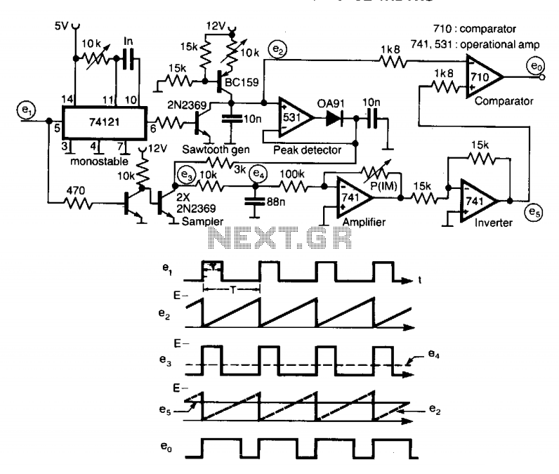
A circuit designed to multiply the width of incoming pulses by a factor that can be greater or less than unity is straightforward to construct. It features a single adjustable potentiometer for selecting the multiplying factor. This factor is...
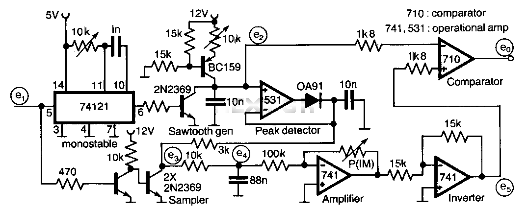
This circuit is designed to multiply the width of incoming pulses by a factor that can be either greater or less than one. It is straightforward to construct and features a single potentiometer for adjusting the multiplying factor. The...
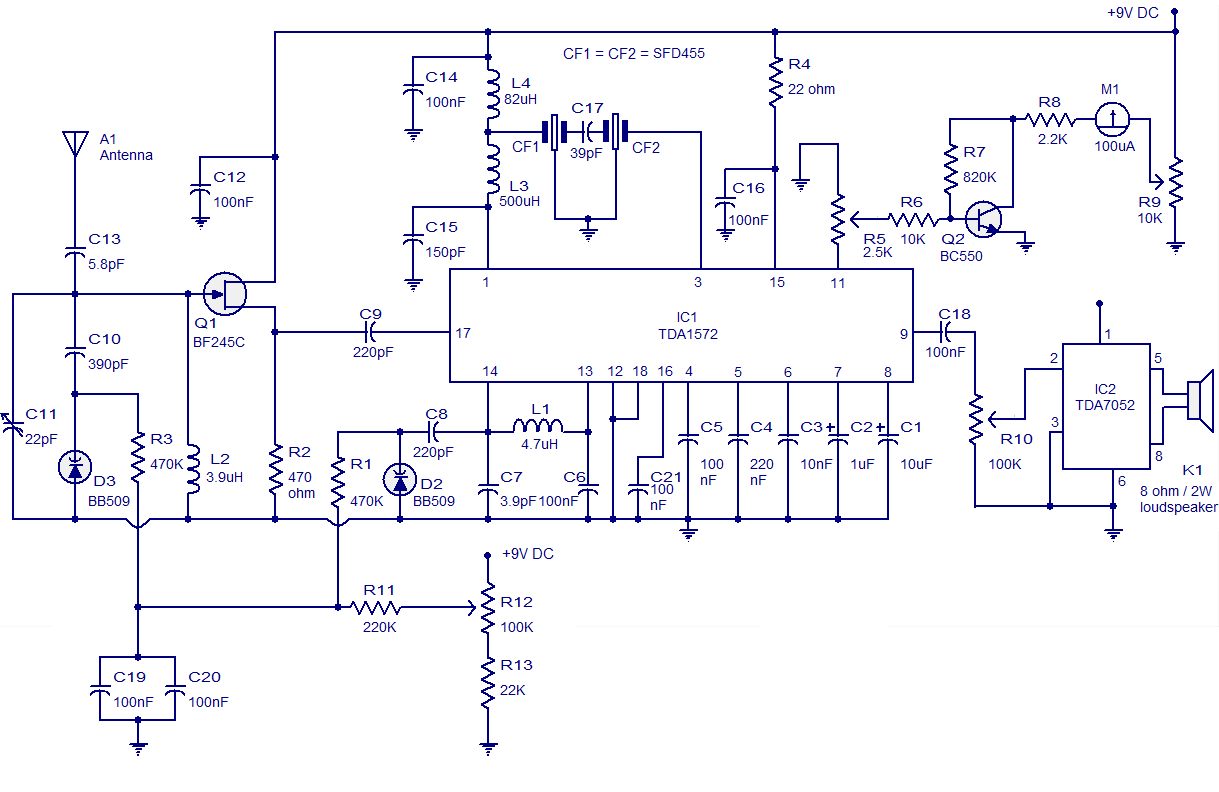
High-quality AM radio circuit based on the TDA1572 IC. The AM radio receiver circuit operates from 9V DC and has a 1W output power. It requires a minimum number of external components. The AM radio circuit utilizing the TDA1572 integrated...
The second 555 timer was configured as a monostable circuit, commonly referred to as a one-shot since an output pulse only occurs if there is a trigger on the input. When this timer is triggered, the potentiometer in the...
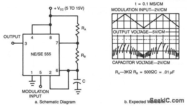
This application utilizes a timer configured for astable (free-running) operation, with a modulating signal applied to the control voltage terminal. The pulse position changes in accordance with the modulating signal, as both the threshold voltage and the time delay...
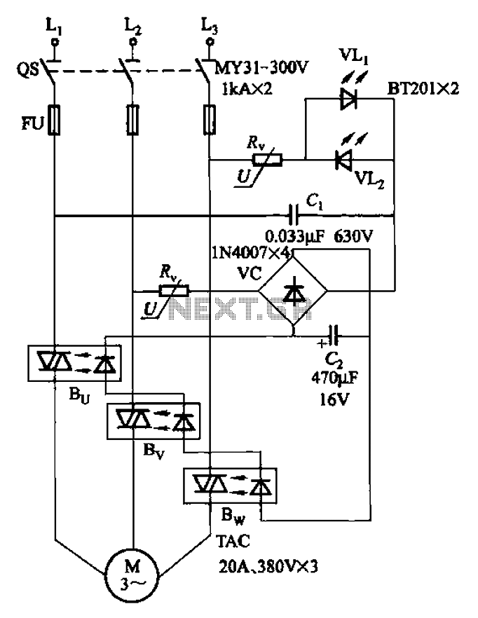
The circuit depicted in Figure 3-93 is integrated with an optical phase sequence protection relay. The circuit in question is designed to provide phase sequence protection using an optical relay mechanism. Optical phase sequence protection relays are crucial in applications...