Pulse Rate Monitor

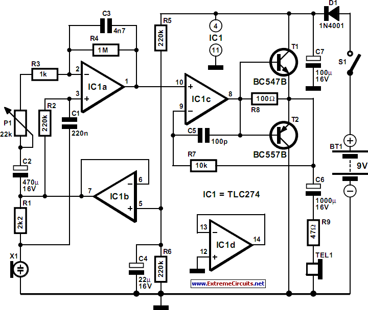
This simple circuit allows for the monitoring of one's heartbeat, particularly useful during exercise. The transducer employed for pulse detection is an electronic component.
This circuit typically incorporates a photoplethysmogram (PPG) sensor as the transducer to detect changes in blood volume in the microvascular bed of tissue. The PPG sensor operates by emitting light, usually from a light-emitting diode (LED), which penetrates the skin and illuminates the underlying blood vessels. The light is then partially absorbed by the blood, and the variations in light intensity detected by a photodetector correspond to the heartbeat.
The circuit design includes an operational amplifier to amplify the small signals generated by the PPG sensor, ensuring that the heartbeat signal is strong enough for further processing. A band-pass filter is often integrated into the design to eliminate noise and interference from other physiological signals and ambient light, allowing for a clearer representation of the heart rate.
The output from the amplifier can be connected to a microcontroller or a digital signal processor (DSP) for further analysis. The microcontroller can be programmed to display the heart rate on an LCD screen, providing real-time feedback to the user. Additionally, the circuit may include a battery management system to ensure that it operates efficiently during prolonged use, especially during physical activities.
Overall, this heartbeat monitoring circuit is a practical application of electronic components in health and fitness, enabling users to track their heart rate effectively while engaging in exercise.This simple circuit enables you to listen to your heartbeat, for instance, while you are exercising. The transducer used for detecting the pulse is an ele.. 🔗 External reference


