
Pulse Train
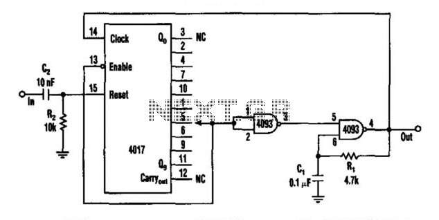
The circuit operates by leveraging the characteristics of the 4093 Schmitt trigger, which provides a stable oscillation due to its hysteresis properties. The Schmitt trigger generates a square wave output that serves as the clock signal for the 4017 decade counter. The 4017 is designed to count from 0 to 9 and produces a high output on each of its ten output pins sequentially with every pulse received.
The reset function of the 4017 is crucial for controlling the counting sequence. When a pulse is applied to the input capacitor C2, the 4017 is reset, setting the count back to zero. This action ensures that the output zero is the first to go high, while all other outputs (1 to 9) are low. The oscillator then starts generating pulses, allowing the 4017 to increment its count.
As the 4017 counts, it outputs high signals on pins corresponding to its count value. When the output reaches any of the pins connected to the 4093's input (pins 1 or 2), a high signal is fed back to the Schmitt trigger, inhibiting further oscillation. The output of the 4093 remains high until the next pulse arrives at the input, effectively pausing the counting process until the circuit is reset again.
This design can be employed in various applications, including frequency division, timing circuits, or as a component in more complex digital systems. The combination of the Schmitt trigger and decade counter allows for precise control over pulse generation and counting, making it suitable for tasks that require accurate timing and sequencing. This circuit has a rate multiplier using a 4093 Schmitt trigger as an oscillator, driving a 4017 decade counter. When a pulse p resent at the input (to C2) 4017 is reset, output zero goes high, and outputs 1 to 9 go low. The oscillator (4093) starts running and the 4017 counts the pulses until the 4017 output (1 to 9) connected to pin 1 and 2 of the 4093 goes high. The oscillator is inhibited and the output remains high until the next input pulse. 🔗 External reference
Related Circuits
This is an adaptation of the previously posted bicycle anti-theft alarm. A commenter expressed interest in modifying it for use with a threshold step plate vibration detector. The adaptation of a bicycle anti-theft alarm into a threshold step plate vibration...
The volt-ampere characteristics of a tunnel diode exhibit an S-shaped curve. The peak current point, referred to as point P, represents the maximum current, while the valley point, denoted as point V, indicates the minimum current. Key parameters of...
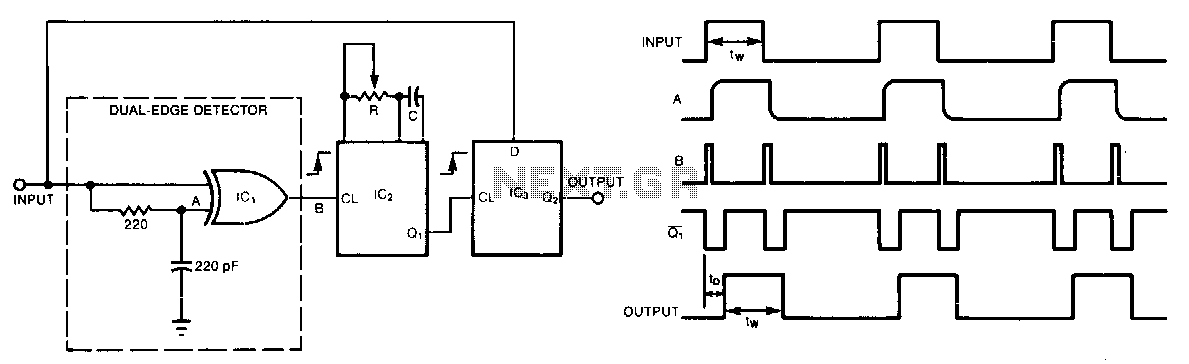
A single monostable multivibrator delays a pulse train by a variable amount; however, this amount cannot be less than the minimum allowed pulse width. The exclusive-OR gate, IC1, generates a short pulse following every leading or falling edge of...

The TLE6282G is an H-Bridge and Half Bridge Driver IC designed for high-current DC brush motor applications in PWM control mode. It is suitable for use in injector and valve applications across 12V, 24V, and 42V power networks. This...

This circuit must be used between the drive voltage of such a transformer and track. On JP1, the transformer is connected to JP2, the rails are connected to JP3, is a TTL "High" position when there is a tax...
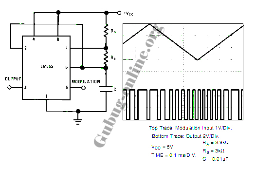
This design circuit for a pulse position modulator can be easily constructed using a 555 integrated circuit (IC). The pulse position modulator modulates the on-period while maintaining a fixed off-period. The circuit utilizes the 555 timer IC in astable mode...