
Pulse Position Modulator Circuit
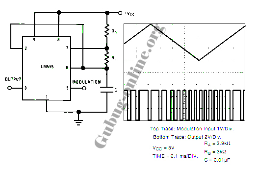
The circuit utilizes the 555 timer IC in astable mode to generate a series of pulse signals. In this configuration, the timing components, namely resistors and capacitors, determine the frequency and duty cycle of the output waveform. The output frequency can be adjusted by varying the values of these components, enabling the modulation of the pulse width.
In pulse position modulation (PPM), the position of the pulse is varied while keeping the duration of the off-period constant. This technique is particularly useful in applications such as remote control systems and communication devices, where the timing of the signal can convey information.
The 555 timer operates by charging and discharging a timing capacitor through the resistors connected to its discharge and threshold pins. The output pin generates a square wave, which can be further processed to achieve the desired modulation characteristics. By implementing additional circuitry, such as filters or amplifiers, the PPM signal can be refined for specific applications.
In summary, this circuit design offers a straightforward approach to creating a pulse position modulator using the versatile 555 timer IC, providing a reliable method for signal modulation in various electronic applications.Here s the design circuit for pulse position modulator can be easily built using 555 IC. Here s the figure of the circuit; .Pulse position modulator modulate the on-period while keeping the fixed off-period. Pulse position modulation might subs .. 🔗 External reference
Related Circuits
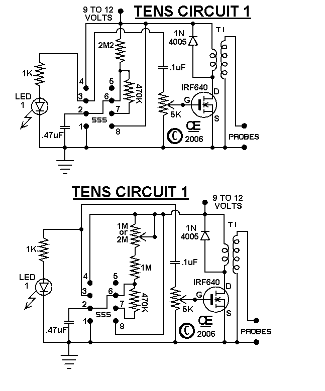
The circuits were originally designed for an individual with muscle issues. Although they were reported to function effectively, the use of these devices is not recommended for anyone, and no responsibility or liability is accepted for their assembly or...
This analog switch circuit is designed to switch an analog line on or off. It consists of two analog switches in integrated circuit (IC) form that are controlled by two pushbuttons. The described analog switch circuit utilizes two integrated analog...

The connection and wiring between each part and component of the exterior lighting system of the vehicle includes elements such as the fusible link, junction block, tail light relay, cruise control, stop light switch, relay box, column switch, rear...

This combination sync stripper and universal video interface can solve various problems, including interfacing Super Nintendo with other devices, video overlay, and locking TV frames for scopes. Kits, fully tested units, and custom cable assemblies are available through Redmond...

An electronic circuit breaker is designed to detect overload conditions and disconnect power when the load exceeds a predetermined threshold. This circuit is particularly suitable for safeguarding Uninterruptible Power Supply (UPS) devices, such as inverters. The electronic circuit breaker operates...
This circuit is a low-frequency Wien bridge sinusoidal oscillator designed for the audio range, characterized by very low distortion, making it suitable for testing various audio equipment. The circuit has undergone thorough testing, and a printed circuit board (PCB)...