
Pulse Signal Generator
The main parameters of the tunnel diode are: (1) Peak point voltage Up is about dozens of millivolt; valley point voltage Uv is about hundreds of millivolt. (2) Peak point current Ipi is about several milliampere; valley point voltage Iv is about hundreds of microampere. (3) Proportion of peak point current and valley point current is about 5-6; the higher, the better. (4) Valley point capacitance Cv of from several microfarad to dozens of microfarad, and the lower, the better; 2BS4A made in China: Up=80 millivolt, Ip = 4 milliampere, valley point current proportion ‰¥5, Cv = 10 ½ 15 microfarad, Uv = 280 millivolt.
(View) Pulse and pulse train generator is mainly composed of a CD4093 four - two input terminals Schmitt trigger and a button switch. When people press the button, the circuit outputs a single pulse, when people press the button for a period of time, the circuit will output the pulse train.
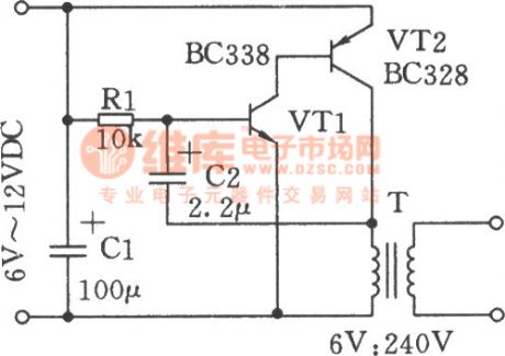
The circuit is shown as the chart. The circuit consists of push button switch, input control circuit, pulse oscillator and pulse output circuit. (View) The circuit is shown as the chart, it uses the 6V ~ 12V DC power supply to produce high-voltage pulse.
In the circuit, the transistors VTl, VT2 constitute an oscillator to produce a DC pulse voltage with the frequency in 3Hz, and it has the primary coil of booster with the output transformer ratio in 6V: 240V, and after each pulse ends, the secondary coil of corresponding transformer will generate a high voltage level. Pulse repetition frequency can be selected by adjusting C2, Rl. When the circuit is used in the baton, it can use lead-acid batteries. (View) The Simple Pulse Signal Generator Circuit Composed Of 74LS00 is shown in the picture below. This Signal Generator uses mainly two TTL integrated circuit (74LS00) to generate t=4us pulse signal.
Its components used is just a few so that it is easy foradjustment andmaintenance. (View) Logic pulse generator can transport either positive or negtive logic pulse according to the need, the circuit is as shown. The circuit consists of a four - two input NAND gate CD4011, of which the door Dl, D2 form a RS trigger pulse, D3, D4 are used as inverters.
It isolates the output of D1 and then drives a light-emitting diode after reversing, it is used to indicate the logic state of the output pulse. (View) Pulse frequency depends on the size of the capacitance C, according to need can use 0. 1uF or other value. 12K © resistance is load resistor required by operational amplifier open collector. (View) In digital circuits, sometimes it needs pulse a divider circuit which could minus a few input pulse.
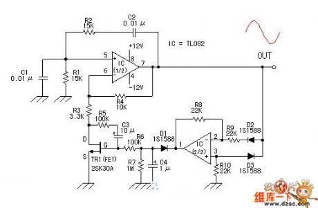
The appropriate combination ofCD4013 and feedback door can achieve any pulse subtraction circuit. Figure 3-1 shows 3-1 count down circuit composed of CD4013. (View) When general pulse generator adjust its oscillation frequency, the signal pulse width is also changed. Conversely, when it needs to change the pulse width, the oscillation frequency is changed. The circuit can make the pulse width and frequency be adjusted separately, they are independent from each other.
The circuit shows in Fig. (View) The PLL pulse generator is shown as the chart. The circuit is the phase-locked loop (PLL) pulse generator circuit. PLL makes a fractional frequency to crystal oscillator and gets 1kHz stepped frequency signal, moreover, it obtains 10kHz 999kHz pulse waveform on the output terminal. The manifold block 74HC4060 is a type of integrated chip with NOT gate and 1/2n frequency dividing circuit inside, among them, the NOT gate and the crystal oscillator with 4.
096MHz form a oscillator circuit, and the frequency dividing circuit gets lkHz reference f 🔗 External reference
Related Circuits
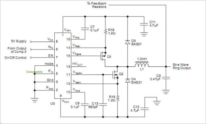
The HV739 is a monolithic single-channel, high-speed, high-voltage ultrasound transmitter pulser. This integrated, high-performance circuit is housed in a single 5x5 mm, 32-lead QFN package. The HV739 can deliver up to ±3.0 A of source and sink current to...
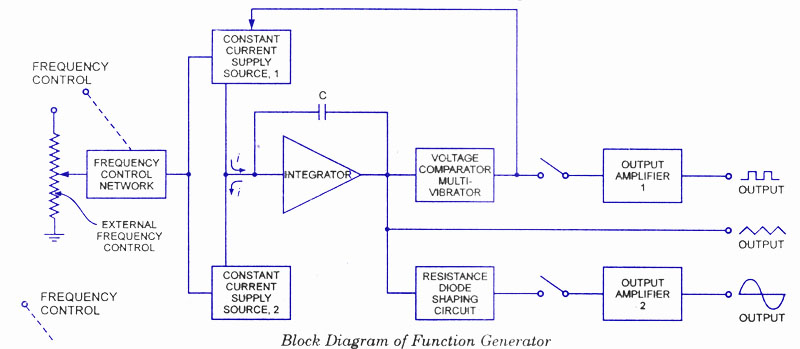
A function generator is a signal source capable of producing various types of waveforms as its output signal. The most common output waveforms include sine waves, triangular waves, square waves, and sawtooth waves. The frequencies of these waveforms can...
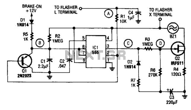
The STS schematic illustrates a circuit designed to alert a driver when the turn signal has been active for more than 15 seconds. The voltage at the gate of transistor Q2 increases in response to the charge accumulated on...
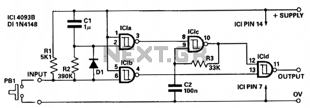
The circuit provides independent control of the initial delay and pulse rate. ICIc functions as a pulse generator, with its operation inhibited by the normally low output of ICla. When the circuit input transitions to low (e.g., when pressing...
The circuit is capable of changing the frequency range, with the oscillating signal adjustable via potentiometer RP1. The output resistance is low (1 kΩ), making it suitable for various control circuit applications as a signal source. In this design,...
This circuit is designed for low-power transmitters that operate with a positive keying voltage. The transistors Q1, Q2, and Q3 are configured as a switching amplifier. When the key is pressed, the collector of Q3 connects to ground, which...