
Pulsed Charger for Lead Acid batteries (NE555)
The project: get hold of an old charger, big or small it’s your choice depending on the size of batteries you normally handle (bigger is better). There are some tricks to boost the performance if you need it. Start by ripping out everything except the transformer and the rectifier. Some older chargers are equipped with fin rectifiers, which have high voltage drop and must be replaced. Replace with a rugged bridge rectifier that can cope with the amperes. All wiring on secondary should be short and heavy wire. The rectifier should be bolted to the chassis to keep cool. If the charger has a high/low switch it’s a bonus, if not you can in some cases add a few turns of wire on the secondary winding. The circuit; a 14-stage ripple counter and oscillator IC 4060 produce a pulse, which is the heartbeat of the circuit. The pulse is fed to the 555 timer that decides the length of the active output. With the switch, you can select long or short pulse output. The output of the 555 timer triggers the zero-cross optoisolator triac driver MOC 3041 via a transistor. This gives the charger transformer a soft start via the triac and the snubber circuit. A small power supply is necessary for the circuit and consists of T1 a transformer 15V 0.1A secondary, a bridge rectifier, a regulator, and two capacitors. Because this project includes a charger, the outcome can differ in performance from one case to another. However, this does not mean that the project doesn’t work, but the efficiency can vary. Some notes: the snubber capacitor is a high voltage AC type and the resistors on the mains side are at least 0.5W type. Use a triac that can take 400V+ and 10A+, BTA 25.600 is suggested as it is robust, though it may be overkill in most cases.
The circuit design aims to address the issue of lead-acid battery sulphation by applying a controlled charging pulse. The 555 timer is configured in a monostable mode, allowing for adjustable pulse widths, which can be set to either long or short durations based on the operational requirements of the battery being charged. The 14-stage ripple counter and oscillator IC 4060 generates a clock signal that drives the 555 timer, ensuring precise timing for the charging pulses.
The use of a triac driver, specifically the MOC 3041, facilitates the control of AC power to the charger transformer by providing isolation between the low-voltage control circuit and the high-voltage AC circuit. This enhances safety and allows for a soft start mechanism, reducing inrush current and prolonging the lifespan of the transformer and associated components.
The design also incorporates a snubber circuit to protect the triac from voltage spikes, which can occur during switching. The choice of components, including a robust bridge rectifier and heavy gauge wiring, ensures that the circuit can handle the necessary current without overheating or suffering from excessive voltage drops.
Overall, this circuit modification provides an effective solution for restoring lead-acid batteries that have suffered from sulphation, enhancing their performance and extending their usable life. However, it is crucial to monitor the charging process closely to avoid overheating and ensure optimal results. The object is to get the cell voltage high enough for the sulphate to dissolve without boiling or melting the battery. This is achieved by applying higher voltage for shorter periods and let the battery rest for a while.
The pulses on short range is about 0.5s on / 3s off and the long pulse range is 1.4s on / 2s off. These times can vary depending on component tolerances. Start on long pulse and if you discover ?boiling? (more than with normal charging) in the electrolyte switch to short puls. Don?t leave the process unattended, at least until you know how your specific version of this project turns out. I built ver.1 of this circuit some 10 years ago and have experimented with it but I?m sure someone can improve it further.
If you own a motorcycle, a motor home, a caravan, a lawn mover, a day cruiser or maybe a vintage car you must at some point had to write off a lead acid battery. When a battery is improperly charged or allowed to self-discharge as occurs during non-use, sulphate crystals build up on the battery's plates.
The sulphate preventing the battery from being fully charged and therefore it is unable to deliver its full capacity. When trying to charge a battery in this state it only gets hot and looses water, the gravity of the electrolyte is not increasing to its normal ?full charge?
state. The only thing you do is killing the battery completely. If a battery has a resting voltage of at least 1.8 Volts/cell and no cells are shorted, desulphation of its plates can be done. This circuit is an add-on and part for a modification of a normal charger and it takes care of the sulphate problem.
The project: get hold of an old charger, big or small it?s your choice depending on the size of batteries you normally handle (bigger is better). There are some tricks to boost the performance if you need it. Start by ripping out everything except the transformer and the rectifier. Some older chargers are equipped with fin rectifiers, which have high voltage drop and must be replaced.
Replace with a rugged bridge rectifier that can cope with the amperes. All wiring on secondary should be short and heavy wire. The rectifier should be bolted to the chassis to keep cool. If the charger have a high/low switch it?s a bonus, if not you can in some cases add a few turns of wire on the secondary winding. The circuit; a 14-stage ripple counter and oscillator IC 4060 produce a pulse, which is the heartbeat of the circuit.
The pulse is feed to the 555 timer that deicide the length of the active output. With the switch you can select long or short pulse output. The output of the 555 timer triggers the zero-cross optoisolator triac driver MOC 3041 via a transistor. This gives the charger transformer a soft start via the triac and the snubber circuit. A small power supply is necessary for the circuit and consists of T1 a transformer 15V 0.1A secondary, a bridge rectifier, a regulator and two caps.
Because this project include a charger that is (X) the outcome can differ in performance from one case to another. However this do not mean that your project doesn?t work, but the efficiency can vary. Some notes the snubbercap is a high voltage AC type (X) and the resistors on the mains side is at least 0.5W type.
Use a triac that can take 400V+ and 10A+, I use BTA 25.600 but this is overkill in most cases. 🔗 External reference
Related Circuits
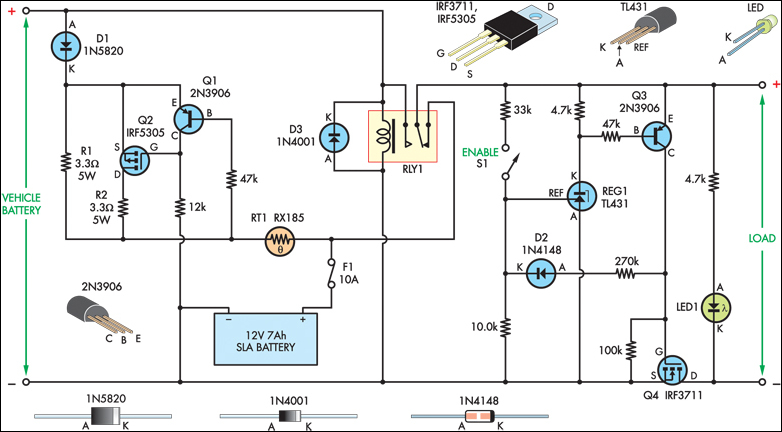
The SLA battery is charged from the vehicle's battery. When the engine is running, the voltage remains fairly constant, which greatly simplifies the charging circuit. If the SLA battery is fully charged, any further charging current from the vehicle...
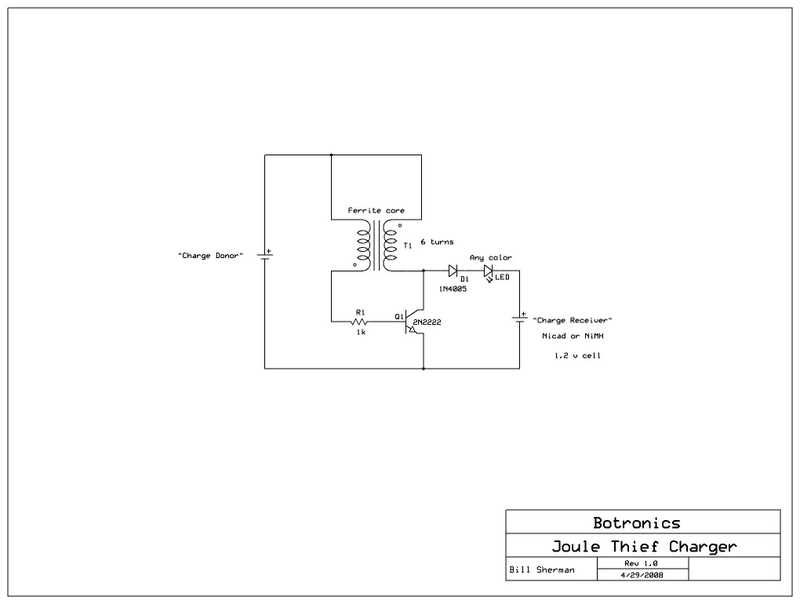
Allow a dead battery to energize another! An open circuit Joule Thief can generate 50 volts or more, sufficient to charge a AA or AAA NiCad or NiMH rechargeable battery. The Joule Thief is a minimalist circuit designed to extract...
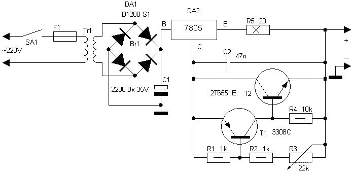
Motorcycle battery charger power supply. Refer to the mentioned page for an explanation of the power supply related circuit diagram. The description of the battery charger indicator: The circuit above enhances the appearance of a simple battery charger, making...
This automotive battery charger project is designed to charge 12V electrolyte lead-acid batteries. The automotive battery charger circuit is engineered to efficiently charge 12V lead-acid batteries, which are commonly used in vehicles. The design typically incorporates several key components, including...
If you have a diverse assortment of 12V batteries in different conditions, this straightforward circuit will enable you to easily assess their capacity. This circuit is designed to evaluate the capacity of 12V batteries, which may be in varying...
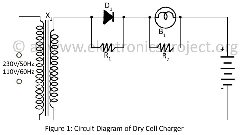
A dry cell charger designed to recharge dry cells 6 to 8 times using a minimal number of components, based on the principle of Periodic Current Reversal (PCR). The circuit diagram is applicable to various projects. The dry cell charger...
Warning: include(partials/cookie-banner.php): Failed to open stream: Permission denied in /var/www/html/nextgr/view-circuit.php on line 713
Warning: include(): Failed opening 'partials/cookie-banner.php' for inclusion (include_path='.:/usr/share/php') in /var/www/html/nextgr/view-circuit.php on line 713