
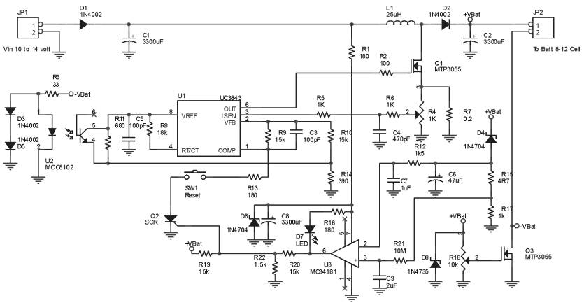
High-Current Battery Discharger
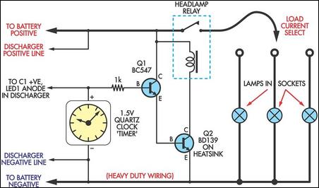
This circuit is designed to evaluate the capacity of 12V batteries, which may be in varying states of health. The schematic typically includes a battery holder, a load resistor, and a voltmeter or an ammeter to measure voltage and current, respectively.
To begin, a battery holder is utilized to securely connect the 12V battery being tested. The load resistor is selected based on the desired discharge rate, which should ideally match the typical load that the battery would experience in practical use. The resistor allows the battery to discharge at a controlled rate, providing accurate readings of its capacity.
The voltmeter is connected across the battery terminals to monitor the voltage drop as the battery discharges through the load resistor. An ammeter may also be included in the circuit to measure the current flowing through the load, which can help in calculating the total capacity in ampere-hours (Ah).
To perform the capacity test, the battery is connected to the circuit, and the load is applied. The voltage and current readings are recorded at regular intervals until the voltage drops to a predetermined cutoff level, typically around 10.5V for a 12V battery. This information can then be used to calculate the total capacity of the battery by integrating the current over time.
In summary, this simple circuit provides a practical method for assessing the capacity of 12V batteries, allowing users to determine their viability for various applications. Proper selection of components and careful monitoring of the discharge process are crucial for obtaining accurate capacity readings.If you have a motley collection of 12V batteries in varying states of health, this simple circuit will allow you to easily check their capacity. It s basi.. 🔗 External reference
Related Circuits
This is a battery tester circuit. This circuit is used to indicate whether the level of a battery voltage is normal, under-voltage, or over-voltage. The battery tester circuit is designed to assess the voltage level of a battery and provide...
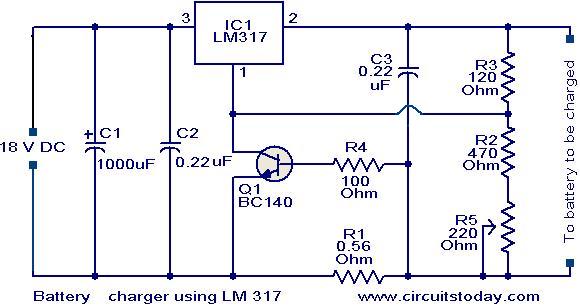
This is a simple yet effective battery charger circuit utilizing the LM317 integrated circuit (IC). The circuit is designed for charging 12V lead-acid batteries and can be easily assembled on a general-purpose printed circuit board (PCB). The core component...
Nokia BL-4C and BL-5C are 3.7V, 700-1000mAh (various) lithium-ion batteries that have three terminals. These terminals include a positive terminal, a ground, and a BSI (Battery Status Indicator) terminal, which presents a fixed resistance value that needs to be...
The Ultra Fast Battery Charger for Nickel-Cadmium (NiCad) battery cells is designed to efficiently charge NiCad batteries. This charger, referred to as the Ultra Fast NiCad Battery Charger, is capable of rapidly filling NiCad battery cells. The charger is...
The circuit diagram depicted in Figure 5 illustrates a system for charging a lead-acid battery using 220V AC power. The circuit employs a capacitor, buck converter, and diode rectifier for this purpose. A red LED indicates the charging status....
Instructions for creating a battery pack for Apple devices powered by standard alkaline batteries are provided. This overview outlines the circuit design for the battery pack, with detailed casing instructions to follow in a subsequent section. Note: When soldering...